Sheet # 692/2u – Electric connectors (F620)
Version 1.04a User guide ATEQ 6th series Page 4/8
2.3. CONNECTOR DEVICENET INPUT OR ANALOG OUTPUTS (OPTION)
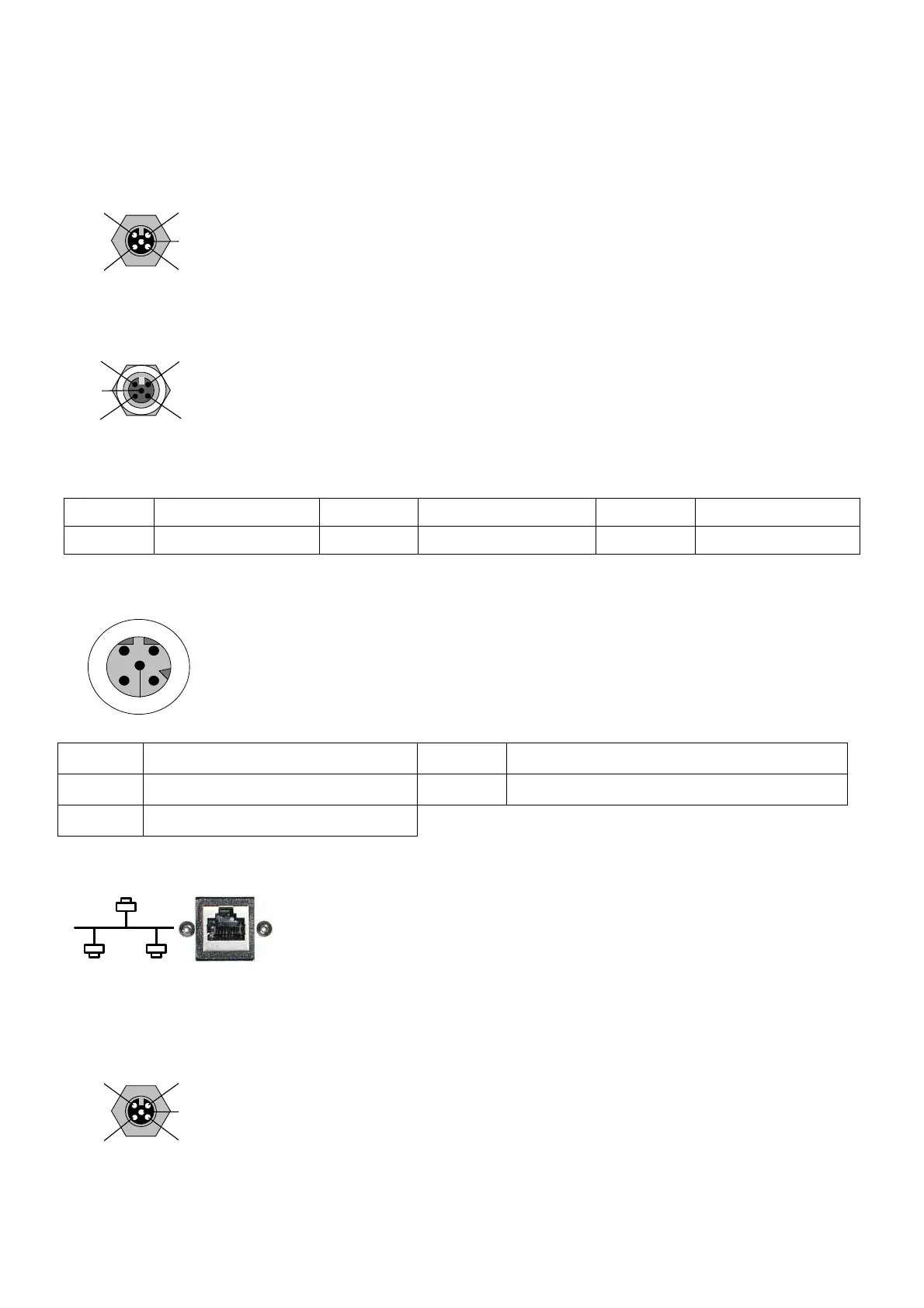
2.3.1. Devicenet Input (option)
2 1
4
3
5
To connect to others ATEQ devices (M12 male connector).
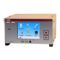
2.3.2. J2 Devicenet output (option)
2
1
4
3
5
To connect to others ATEQ devices (M12 female connector).
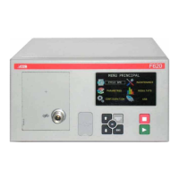
2.3.3. Wiring Devicenet
Pin 1 Drain Pin 3 V- Pin 5 CAN_L
Pin 2 V+ Pin 4 CAN_H
2.3.4. Input and output Profinet
4
3
1
2
5
Ethernet / M12 pin assignement.
M12 female, D coded.
Pin 1 Ethernet Tx + (Transmit Data +) Pin 3 Ethernet Tx - (Transmit Data -)
Pin 2 Ethernet Rx + (Receive Data +) Pin 4 Ethernet Rx - (Receive Data -)
Pin 5
Not used
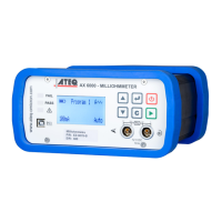
2.3.5. Input and output Ethernet/IP
Standard connection Ethernet TCP / IP protocol.
2.4. ANALOG OUTPUTS (OPTION)
This option is not possible if Devicenet or Profinet options are installed.
Connection for analog outputs.
2 1
4
3
5
¾ Pin 1: sensor 1 (plus).
¾ Pin 2: sensor 1 (minus).
¾ Pin 3: sensor 2 (plus).
¾ Pin 4: sensor 2 (minus).