Page 14
Unity Bulk Feeder C9C Compact, Issue 1
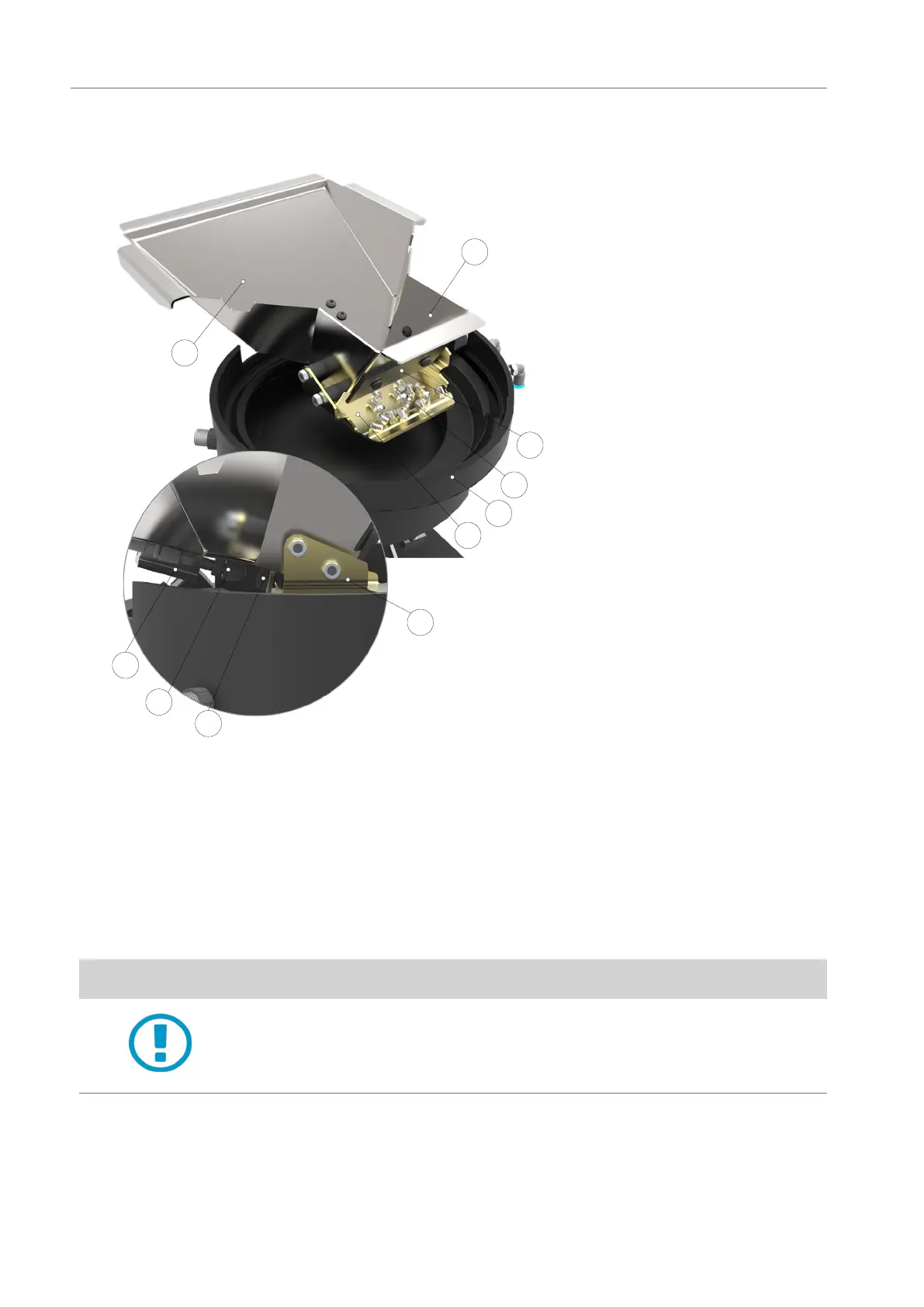
4. 3 Hopper Assembly
1
2
3
4
9
8
4
5
6
7
1 - Hopper chute
2 - Dispensing section
3 - Bae
4 - Dispensing platform
5 - Pneumatic cylinder
6 - Piston
7 - Bumper
8 - Bowl
9 - Rivets
The hopper assembly is located under the plate assembly and there is a cut-out in the plate
for the rivets to enter the hopper chute.
The hopper chute is angled to feed the rivets to the dispensing section of the hopper and
stopped by a bae. The rivets are collected onto the dispensing platform ready for controlled
transfer to the bowl.
The dispenser unit is agitated by a pneumatic cylinder and piston located under the chute for
a xed period and is triggered by the bowl low level sensor.
CAUTION
Always check that the rivet type and size is correct before adding rivets
to the hopper.
Do not ll the bowl directly. Only ll via the hopper
 Loading...