Page 28
Unity Bulk Feeder C9C Compact, Issue 1
5. 3 Electrical Requirements
This unit uses 24V DC and is a ⁄” UNC, 4 pin connector (avilable separately)
Pneumatic Connections
A single pneumatic connection to the inlet lter regulator on the side frame is required.
Connection is by means of an 8mm push t.
A regulator is used to control the ow of air into the control module. The pressure should be set to
6 Bar.
Flow regulators are used to set the air ow rate for the bowl blow settings and for the blow to
feed rivets from the escapement.
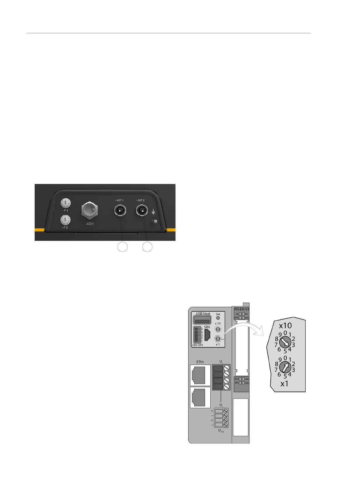
5. 4 Ethernet Connections
12
For the Ethernet IN, XF2 [1] would be
from Unity or a robot
For the Ethernet OUT, XF1 [2] would be
used to daisy chain to another compact
bulk feeder (CBF)
5. 5 Programmable PLC Node Address Setup
Each Compact Bulk Rivet Feeder in a system
has a unique address. The address is set with
two dials on the BL20 Gateway.
The upper dial assigns the node’s x10 (tens)
register, the lower dial assigns the node’s x1
(units) register. In the example opposite node
41 is set.
Compact Bulk Rivet Feeder addresses are as
follows:
Feeder 1A - Node 41
Feeder 2A - Node 43
Feeder 3A - Node 45
Feeder 4A - Node 47
Feeder 1B - Node 42
Feeder 2B - Node 44
Feeder 3B - Node 46
Feeder 4B - Node 48