Page 25
Unity Bulk Feeder C9C Compact, Issue 1
5. 1 T-Tube Installation
CAUTION
Ensure all instructions for T-Tube installation are followed as correct
layout of T-Tube is essential in ensuring the eective supply of rivets.
The rivet feed T-Tube is supplied to length as specied by the customer, normally in 25m rolls.
Check that the T-Tube length is sucient for the installation path and layout. Do not attempt to
join tubes together to increase length.
When planning the T-Tube layout, ensure that the route of the T-Tube is free from all unnecessary
turns and twists and always arrange the T-Tube path with the minimum number of bends. Aim to
keep the T-Tube level throughout its entire length.
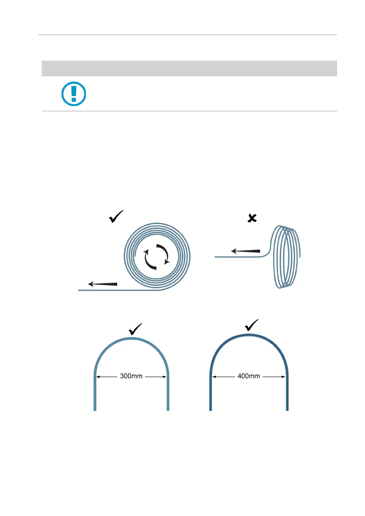
Unroll T-Tube circumferentially from the outermost end. Never take T-Tube spirally from the roll, as
this generates twists along its path and can cause unnecessary strain on T-Tube connections and
possibly damage equipment.
Ensure that T-Tube curvature does not fall below the 300mm minimum diameter for the 3mm
T-Tube and 400mm minimum diameter for 5mm T-Tube.
3mm T-Tube 5mm T-Tube
Check that the T-Tube is not twisted along its axis for more turns than are required; normally a
twist of no more than 90°, from the exit track or selector can be made over T-Tube lengths of less
than 2m. A twist greater than 90° over T-Tube lengths less than 2m, may results in process faults.
For more exposed and vulnerable to damage sections it is advised that the T-Tube is sleeved within
a Ø25mm protective outer tube (conduit). Check that the conduit and T-Tube are not exposed to
any crushing or pinch point hazards e.g. fork lift truck or robot joint.
 Loading...