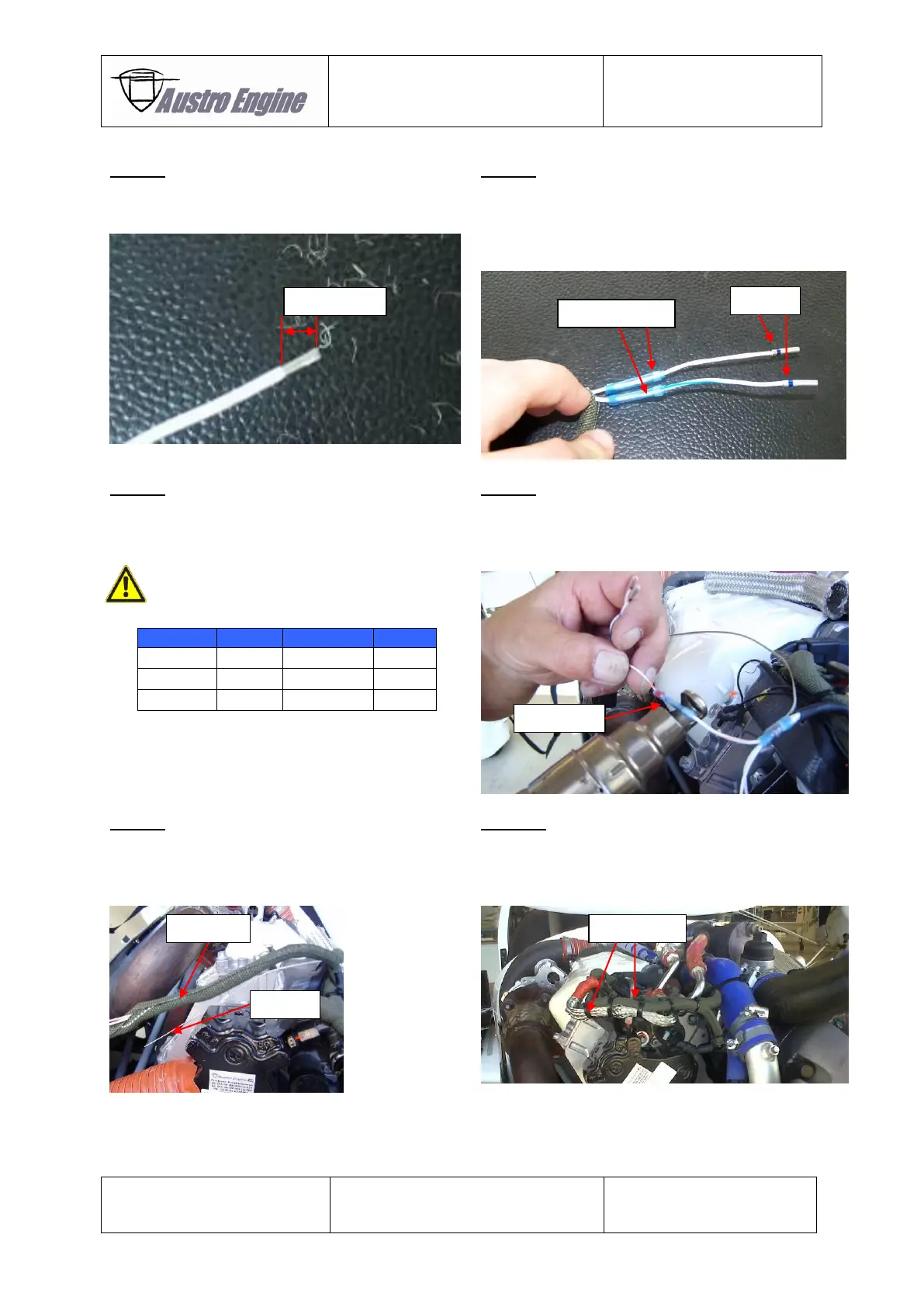
Step 5:
Remove the isolation of all single wires on the end
of the engine harness and the repair kit cable E4A-
90-R18-000 as shown below.
The inline crimp consists of the splice crimp and the
isolation sleeve. Put the isolation sleeve of the inline
crimp over the single wire of engine harness.
Place the splice crimp at the end of the single wires
of the repair kit cable E4A-90-R18-000.
Connect the singles wires of the engine harness
with the repair kit cable of E4A-90-R18-000 by
usage of the inline crimp.
Pinning list for FPS connector is shown in
the table below.
Put the isolation sleeve of the inline crimp over the
inline crimp sleeve. Heat the isolation sleeve (300°C
– 350°C) with a hot air gun until the isolation sleeve
seals the splice crimp and the single wires.
Put the chafing protection ROUNDIT over the
repair kit cable and the engine wiring harness. The
length of the chafing protection ROUNDIT can be
reduced if necessary.
Ensure that the
pig tail is not covered with ROUNDIT and a ring
termination is mounted on it.
Install the additional shielding E4A-95-100-000 as
described in the Installation Manual E4.02.01. The
shielding shall be used as an additional caving
protection.
Cable ties as provided in the repair kit can be used
for fixation.