24-30-20 Installation of the Alternator E4A-91-000-000
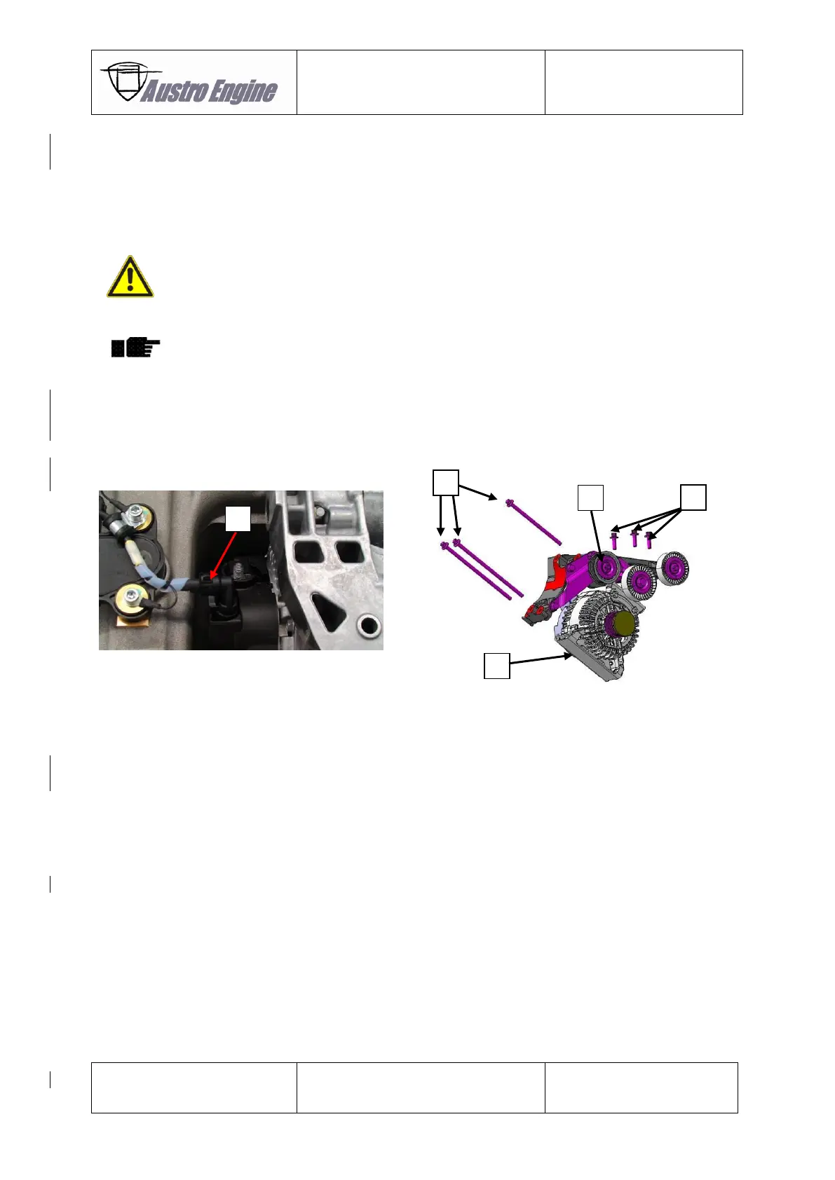
1. Carefully install the Alternator [5] and install the mounting screws [4].
2. Torque the screws [2] and [4] with 20 Nm.
3. Connect the electrical cable marked with “GEN/G2”. Ensure that the connector is
locked.
If the connection is wrong a serious damage to engine is possible.
4. Install the drive belt according to Chapter 85-40-12.
Inspect the drive belt for correct installation.
5. Connect the main battery according to the applicable Aircraft Maintenance Manual.
6. Perform an engine ground run according to the Chapter 71-00-03. Observe the output
voltage of the alternator, which has to be in the typical operating range as described
in the E4 Installation Manual E4.02.01.
Figures for Chapter 24-30-10 and 24-30-20
24-30-30 Inspection of Alternator E4A-91-000-000 and the Carbon Brushes
This chapter describes the steps how to disassemble the alternator and its components
(e.g.: brush holder) for checking the length of the carbon brushes. The criteria for replacing the brush
holder assembly E4A-91-300-000 is also included in this chapter.
The maintenance interval can be found in Chapter 05-20-00 for the E4 engine model and Chapter
05-30-00 for the E4P engine model.