The connector equipped on the harness is a Deutsch AS 008 35 PN. Each compatible
connector can be used on a governor.
Governor Pin Assignment
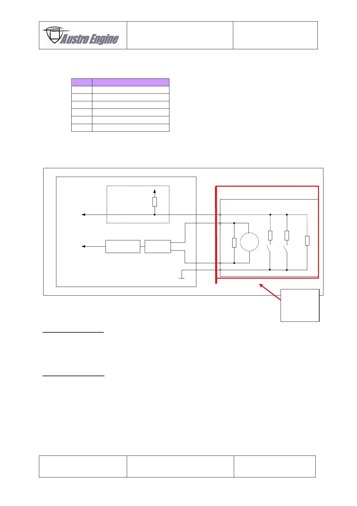
Electrical Drawing Example
EECU E4
H-Bridge
Current
Measurement
Propeller Governor – Actuator Circuit
Input Circuit
M
GND
330R
180R 560R
390R
Left
Stop
Right
Stop
Governor
Stop
Feedback
2K56
Curent
Feedback
Ubatt
Fig. 01 - 25 Electrical Drawing Governor System
EECU Caution Lamp:
Each ECU has its own caution lamp output. The lamp will be supplied with bus voltage via the ECU.
These display lamps are used to inform the flight crew of a detected EECU or Engine failure.
(For particular installation refer to the applicable Aircraft Maintenance Manual)
Power Lever Sensor:
The Power Lever Sensor is a sensor using the Hall-Effect.
It has two independent outputs with different output characteristics which are verified inside the ECU.
Each ECU requires its own sensor. E.g. in a twin engine installation, 4 sensors are necessary.
The installation of the two power lever sensors for the EECU shall ensure that the output signals are
within 5% to each other (e.g. Signal A 85%, Signal B 87%).