AS1635-MT-EN-03
p. 10/46
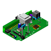
3.3.2. Connectors
Connector FUNCTION
CN1
Main supply (24 VDC) and emergency opening.
Remove the bridge between CN1-3 and 4 to activate the emergency.
CN2 Digital inputs (8 inputs from In1 to In8)
CN3 O-24V terminal (for powering the presence sensors, if present)
CN4 O-24V terminal (for powering the presence sensors if present)
CN5 Digital outputs Out1 and Out2
CN6 Digital outputs Out3 and Out4
CN7 Relay R1 (with potential-free NO and NC contacts)
CN8 Relay R2 (with potential-free NO and NC contacts)
CN9 Relay R3 (with potential-free NO and NC contacts)
CN10 Pictogram, direction B
CN11 Pictogram, direction B
CN12 Not used
CN13 CAN bus (to optional motor card)
CN14 Debug programming (reserved for developers)
CN15 RS232 and RS485 serial communication
CN16 USB port to configuration interface
CN17 Position sensor
3.3.3. The relays
The circuit board AS1635 contains 3 relays whose coils are operated with 24 VDC, delivering potential-free NO and NC
contacts. They can be configured via the configuration interface ( 13. Configuration page, page 31).
3.3.4. The switches
REFERENCE DESCRIPTION
SW1 RUN mode or Programming (restricted to development tream)
SW2 LEFT HMI button
SW3 RIGHT HMI button
SW4 UP HMI button
SW5 DOWN HMI button
SW6 OK HMI button
RST Reset button
USB BOOT Restart the processor via the USB connection
The information contained in this document is the property of Automatic Systems and is confidential. The recipient shall refrain from using this information for any purpose other
than the use of the products or the execution of the project to which it refers and from communicating it to third parties without prior written agreement of Automatic Systems. The
document is subject to change without notice.