AS1635-MT-EN-03
p. 9/46
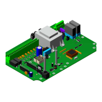
3.3.1. Diagnostic LEDs
REF. DESIGNATION: COLOUR
LD1 DC Voltage available GREEN Steady
LD2 MAJOR error RED Steady
LD3 Minor error YELLOW Steady
LD6 Program running GREEN Flashing
LD8 7-segment display HMI left position RED
LD9 7-segment display HMI middle left position RED
LD10 7-segment display HMI middle right position RED
LD11: 7-segment display HMI right position RED
LD12 Digital input 1 GREEN Steady
LD 13 Digital input 7 GREEN Steady
LD 14 Digital input 3 GREEN Steady
LD15 Digital input 8 GREEN Steady
LD16 Digital input 5 GREEN Steady
LD17 24 DCV available GREEN Steady
LD18: Digital input 6 GREEN Steady
LD19 Digital input 4 GREEN Steady
LD20 Digital input 2 GREEN Steady
LD21 Processor watchdog GREEN Flashing
LD23 Digital output 1 AMBER Steady
LD24 Digital output 2 AMBER Steady
LD25 Digital output 3 AMBER Steady
LD26 Digital output 4 AMBER Steady
LD27 Relay output 1 AMBER Steady
LD28 Relay output 2 AMBER Steady
LD29 Relay output 3 AMBER Steady
LD30 Red-coloured functional pictogram, direction A GREEN Steady
LD31 Green-coloured functional pictogram, direction A GREEN Steady
LD32 Blue-coloured functional pictogram, direction A GREEN Steady
LD33 White-coloured functional pictogram, direction A GREEN Steady
LD34 Red-coloured functional pictogram, direction B GREEN Steady
LD35 Green-coloured functional pictogram, direction B GREEN Steady
LD36 Blue-coloured functional pictogram, direction B GREEN Steady
LD37 White-coloured functional pictogram, direction B GREEN Steady
LD38 CAN Bus GREEN Flashing
The information contained in this document is the property of Automatic Systems and is confidential. The recipient shall refrain from using this information for any purpose other
than the use of the products or the execution of the project to which it refers and from communicating it to third parties without prior written agreement of Automatic Systems. The
document is subject to change without notice.