AS1635-MT-EN-03
p. 11/46
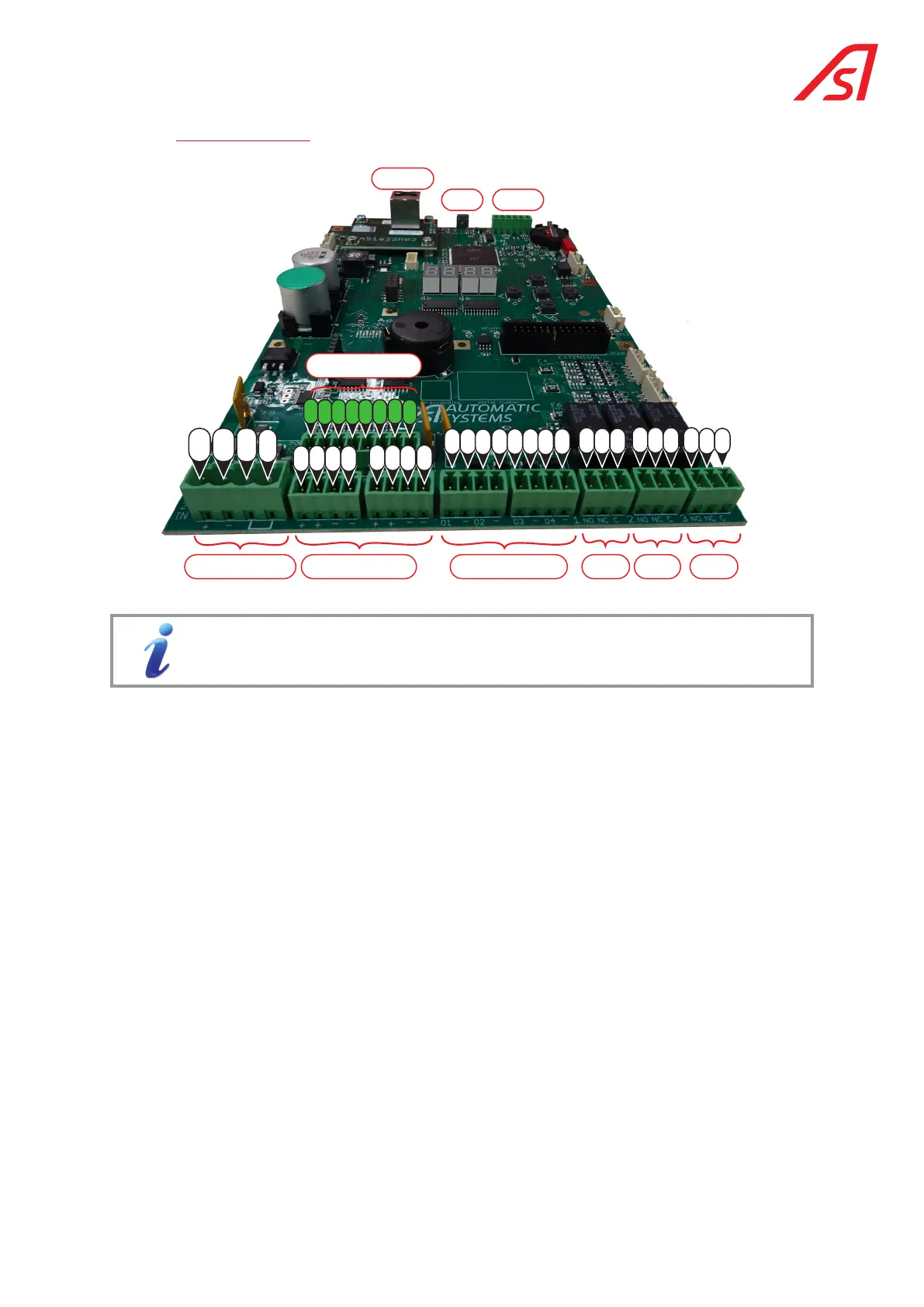
3.3.5. Terminal block
24V
GND
EMG
EMG
E1
24V
24V
24V
24V
GND
GND
GND
GND
OUT1
GND
OUT2
GND
OUT3
GND
OUT4
GND
E2
E3
E4
E5
E6
E7
E8
Power supply
Digital Inputs
Sensors power supply
Ethernet
Relay 2
Relay 3
Digital Outputs
Relay 1
COM
NC
NO
COM
NC
NO
USB
RS232/485
COM
NC
NO
For more information regarding the connection to the circuit board, please refer to the
electrical circuit diagram, Ch.18, page 43.
The information contained in this document is the property of Automatic Systems and is confidential. The recipient shall refrain from using this information for any purpose other
than the use of the products or the execution of the project to which it refers and from communicating it to third parties without prior written agreement of Automatic Systems. The
document is subject to change without notice.