AS1635-MT-EN-03
p. 7/46
3. DESCRIPTION
3.1. terminology
AS Automatic Systems.
CMD Command
DI Digital input
DO Digital output
I/O Input / Output
O/S Out of Service
HMI Man Machine Interface
CRA Card reader direction A
CRB Card reader direction B
NC Normally closed(contact)
NO Normally open(contact)
OP Opening
MVT Movement
TOR All or nothing
Direction A By convention, direction A is the direction of passage for which the main housing
(containing the main power supply) is located to the right of the passage.
Direction B Passage in opposite direction to direction A (the main housing is on the left).
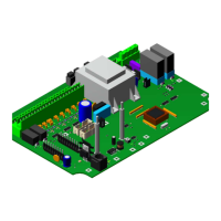
3.2. tecHnical specifications
Power supply 24 VDC ± 10%
Consumption *: < 5 W
CPU ARM CORTEX M3 / M4
Inputs 8 digital inputs 0- 24 VDC
Outputs 4 digital outputs 24 VDC, max. 2A (max. 6 A in total)
Relays
3 relays with NO and NC contacts - maximum rated voltage of 125 VDC, 125 VAC - max.
switching power 60 W.
Connection(s) 1x micro-USB of 12 Mbps at full speed.
1x RS485 for communication with a customer reader.
1x RS232 for communication with a customer reader.
1x CAN line for communication with the motor control card.
HMI
Embedded simplified version with digital display, consisting of 4 x 7-segment LEDs and
5 push-buttons. .
* Without extension board and with the digital outputs and relays OFF.
The information contained in this document is the property of Automatic Systems and is confidential. The recipient shall refrain from using this information for any purpose other
than the use of the products or the execution of the project to which it refers and from communicating it to third parties without prior written agreement of Automatic Systems. The
document is subject to change without notice.