Figure 24: Removing the G430 cover screw from the top of the device
Table 4: Figure notes:
a. G430 top cover screw
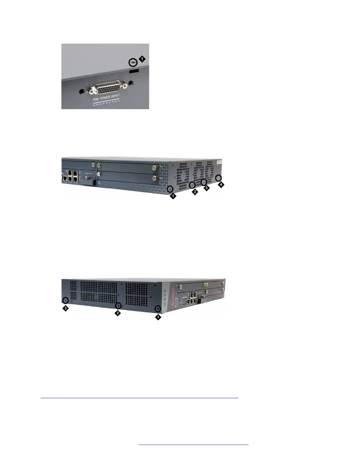
Figure 25: Removing G430 cover screws from the right side
Table 5: Figure notes:
a. G430 right-side cover screw
b. G430 right-side cover screw
c. G430 right-side cover screw
d. G430 right-side cover screw
Figure 26: Removing G430 cover screws from the left side
Table 6: Figure notes:
a. G430 left-side cover screw
b. G430 left-side cover screw
c. G430 left-side cover screw
Related links
Inserting or removing an MP10, MP20, MP80, or MP120 VoIP module on page 74
Upgrading and replacing Field Replaceable Units
February 2017 Installation and Upgrades for the Avaya Branch Gateway G430 76
Comments on this document? infodev@avaya.com
 Loading...


