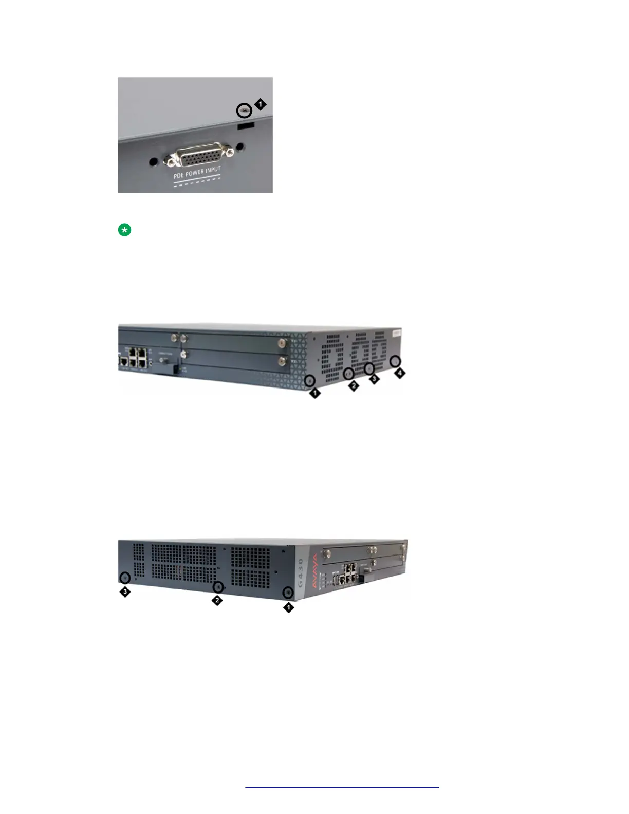
Figure 23: Removing the G430 cover screw from the top of the device
Note:
POE POWER INPUT connector is not present in G430(v2 or v3).
Table 4: Figure notes:
a. G430 top cover screw
Figure 24: Removing G430 cover screws from the right side
Table 5: Figure notes:
a. G430 right-side cover screw
b. G430 right-side cover screw
c. G430 right-side cover screw
d. G430 right-side cover screw
Figure 25: Removing G430 cover screws from the left side
Upgrading and replacing Field Replaceable Units
July 2018 Deploying and Upgrading Avaya G430 Branch Gateway 68
Comments on this document? infodev@avaya.com
 Loading...


