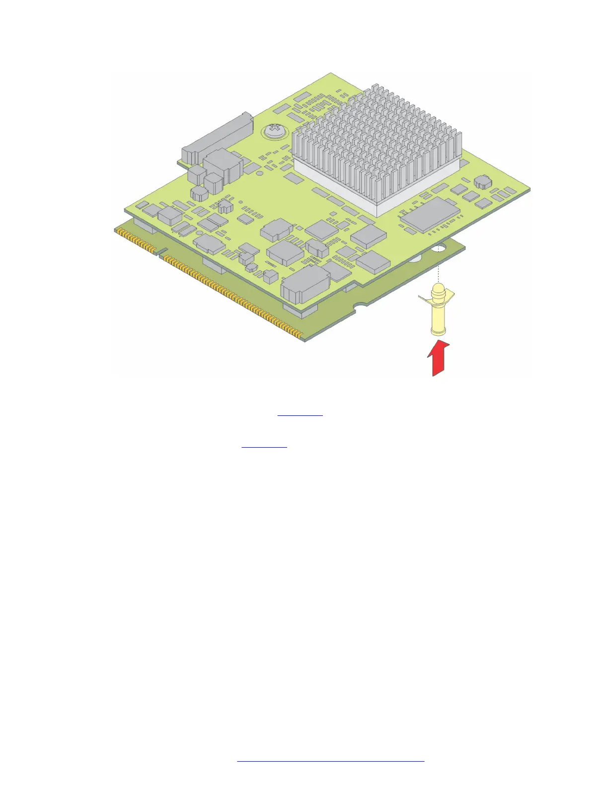
Figure 26: Insert plastic standoff
2. Locate the VoIP module slot (see the figure on page 71).
3. Position the VoIP module at a 45 degree angle to the main board, and start inserting it into
the VoIP module slot (see
the figure on page 71).
Upgrading and replacing Field Replaceable Units
July 2018 Deploying and Upgrading Avaya G430 Branch Gateway 70
Comments on this document? infodev@avaya.com
 Loading...


