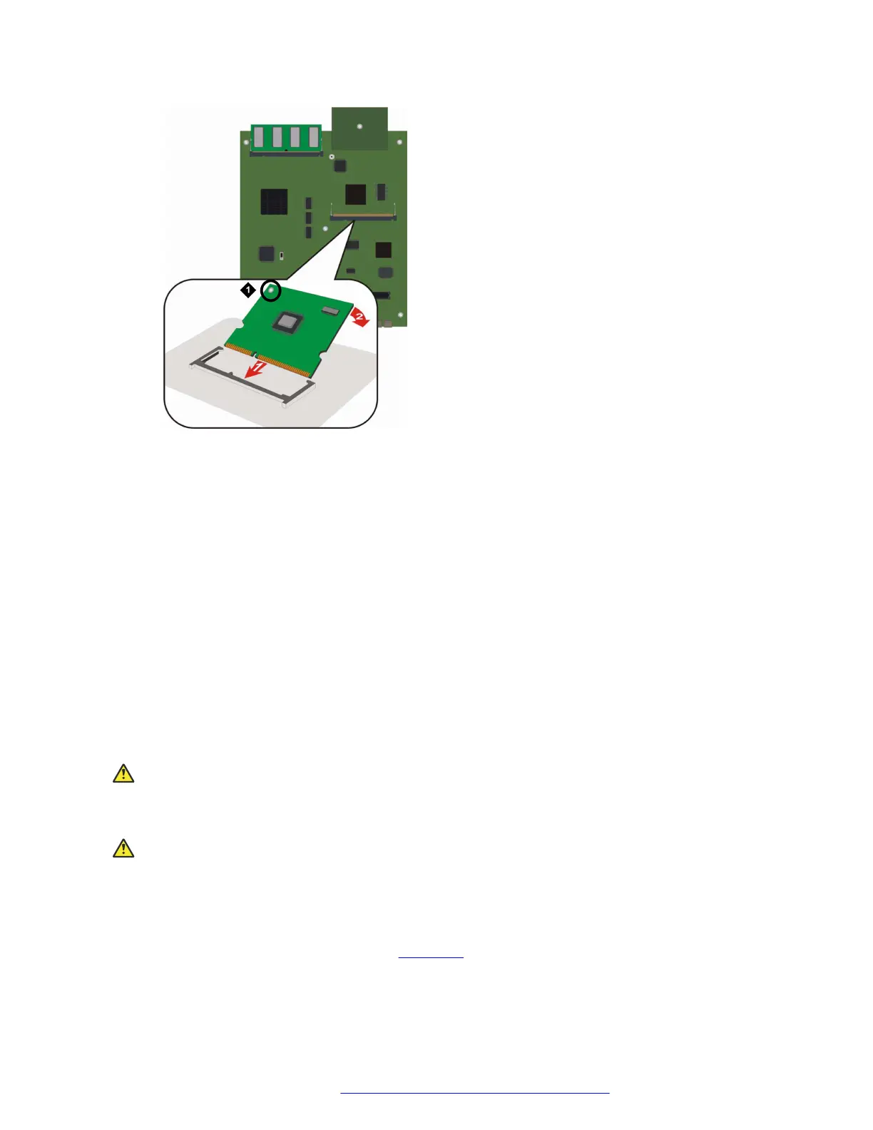
Figure 27: Inserting a VoIP module into the VoIP module slot
Table 7: Figure notes:
a. VoIP module locking screw
4. Push the module in all the way.
Do not use too much force.
5. Flatten the module so it is flush with the main board.
The latches at both sides click shut.
6. Tighten the locking screw affixed to the VoIP module.
This secures the VoIP module to the motherboard.
Removing a VoIP module
About this task
Electrostatic alert:
Hold the module only by its edges to avoid damage from static electricity. Do not touch the top
or bottom of the circuit board. If possible, wear a wrist-strap and use an anti-static bag.
Caution:
The connector pins can be bent or damaged if the module is handled roughly, or if misaligned
and then forced into position.
Procedure
1. Locate the VoIP module slot (see the figure on page 69).
Field Replaceable Unit upgrades and replacements
July 2018 Deploying and Upgrading Avaya G430 Branch Gateway 71
Comments on this document? infodev@avaya.com
 Loading...


