Chapter 2: Modules and Configuration Overview 7
Channel Modules
Channel modules combine to form the fader strips of the system, and include the Fader, Process, Knob, and Display Module. Not
all configurations include each type of channel modules.
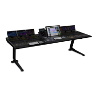
Fader Module
Each Fader Module provides eight channel faders with meters and other con-
trols. Fader Modules are installed in the first slot of each chassis (closest to
the front).
Process Module
Each Process Module provides eight channel strips, each with a knob, OLED
displays and other controls.
Knob Module
Each Knob Module provides eight channel strips, each with four dual-func-
tion (rotate/press) encoders, OLED displays, and other controls. Up to two
Knob Modules can be installed in each chassis (in the larger M40 systems
only). M10/M10 Plus systems support one additional Knob Module for Ex-
pand Zones (Attention Track Knob Module), while M40- and Master Mod-
ule Universal-based systems support two Attention Track Knob Modules.
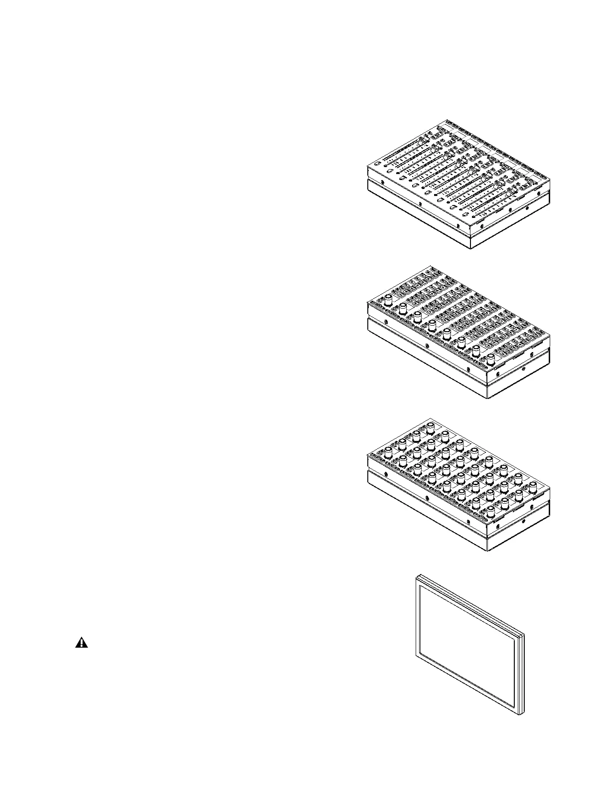
Display Module
(M40 and M10 Plus Systems Only)
Display Modules are installed above channel modules. Each Display Module provides a
large display that shows names, meters, waveforms, and other data for up to eight strips.
Display Modules can also be designated as Master Meter Modules.
The S6 frame is designed to ensure adequate ventilation and cooling for the Display
Module. If you are installing a Display Module in a custom (non-Avid) frame, be sure
that the frame does not obstruct the Display Module air vents. Any unit that has been
installed in a custom frame will have its warranty voided if the fault is found to be due
to insufficient ventilation.
 Loading...
