Chapter 5: Installing Power and Connectivity 49
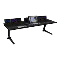
3 From the inside of the chassis, use four more flathead Phillips screws to secure the right Side Cover to the frame as shown in
Figure 32.
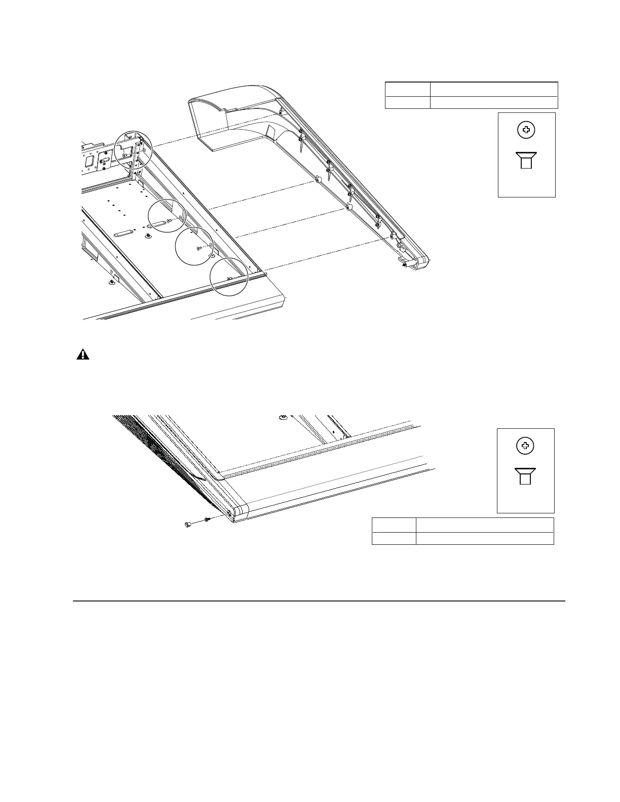
4 After the Side Covers are attached to the chassis secure them to each end of the Bolster using the included fasteners (one per Side
Cover), then insert the included plug to conceal the fasteners as shown in Figure 33.
5 Repeat step 4 for the right Side Cover.
How to Proceed
After assembling the frame and installing the Ethernet switch, PSUs and cabling, proceed to Chapter 6, “Installing Modules.”
Figure 32. Attaching the right Side Cover (switch, PSUs and cables not shown)
Never attempt to move or lift a chassis (any size) by the Side Covers, Bolster, or Rear Panels (they can break). Move or lift while
holding on to the metal chassis (frame) instead.
Figure 33. Securing the left Side Cover the Bolster
(Not to scale)
M4x14 FHPH (7760-30622-00)
Fastener
#2 Phillips
Tool
(Not to scale)
M4x10 (7760-30535-00)
Fastener
#2 Phillips
Tool
 Loading...
