Avid S6 Installation Guide36
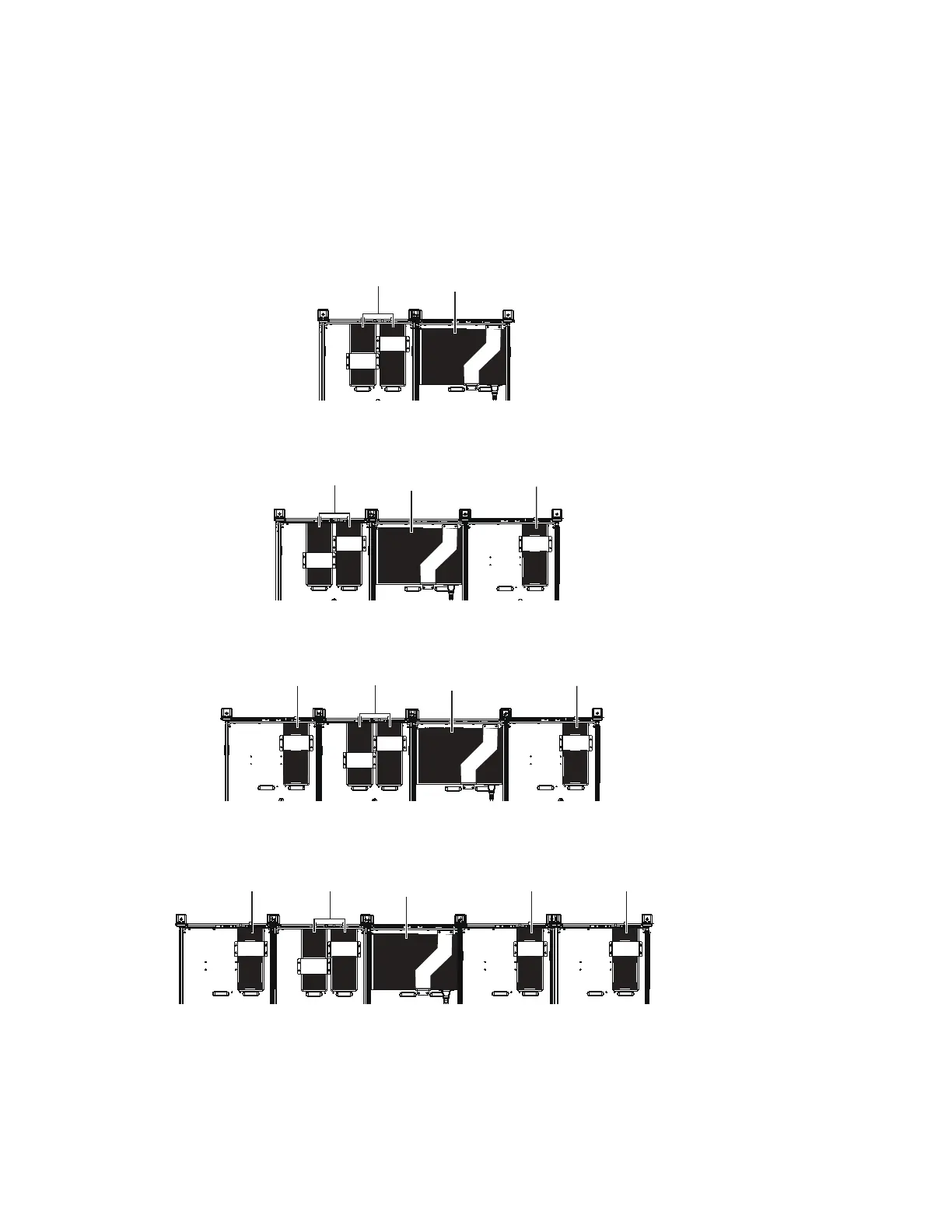
Switch and PSU Placement for Avid-Configured S6 Systems
These diagrams show switch and PSU placement for all frame widths available with Avid-configured S6 systems, which range in
size from 8-fader/two chassis (such as an S6 M10-8-5) up to 32-fader/five chassis (such as an M40-32-9-D). Use these diagrams
to determine where to place units, then proceed to “Installing the Ethernet Switch” on page 38.
For systems that include a Producers Desk, make sure you have read “If Your System Includes a Producers Desk” on page 35.
For larger (custom) configurations see “Switch and PSU Placement for Custom S6 Configurations” on page 37.
2–Chassis Systems
3–Chassis Systems
4–Chassis Systems
5–Chassis Systems
Ethernet switch and PSU placement for an two-chassis, 8-fader system (cables not shown)
Ethernet switch and PSU placement for a three-chassis, 16-fader system (cables not shown)
Ethernet switch and PSU placement for a four-chassis, 24-fader system (cables not shown)
Ethernet switch and PSU placement for an example five-chassis, 32-fader system (cables not shown)
Ethernet switch
PSUs (2)
Ethernet switch
PSUs (2)
PSU
Ethernet switch
PSUs (2)
PSUPSU
PSU
Ethernet switch
PSUs (2)
PSUPSU
 Loading...
