APPENDIX 6 PIN CONFIGURATION
76
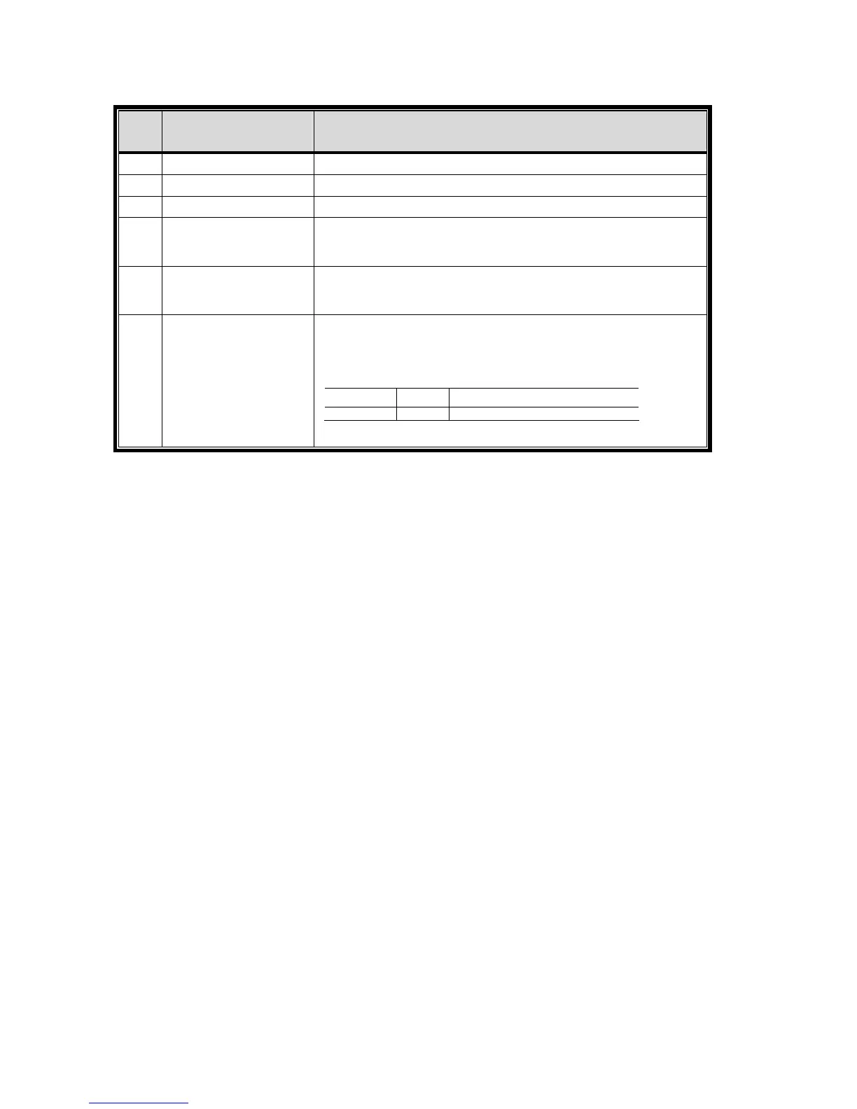
‧ Per modelli 4CH con uscita HDMI
PIN FUNZIONE DESCRIZIONE
1 GND TERRA
2 RS485-A
3 RS485-B
4
ALLARME ESTERNO
COM
In condizioni normali, COM si disconnetta senza NO, ma quando
viene fatto scattare l'allarme, COM si collega con NO.
Attenzione: la tensione è limitata a meno di CC 24V 1A.
5
ALLARME ESTERNO
NO
In condizioni normali, COM si disconnetta senza NO, ma quando
viene fatto scattare l'allarme, COM si collega con NO.
Attenzione: la tensione è limitata a meno di CC 24V 1A.
6 INGRESSO ALLARME
Collegare l’INPUT ALLARME
(PIN 6) e il connettore GND (PIN 1)
con i fili. Una volta fatto scattare l’allarme, il DVR inizierà la
registrazione e l’allarme si attiverà.
PIN Alarm Corresponding video channel
PIN 6 1 CH1
*