Advanced DVB-S2 Receiver Operational Manual
SR1 Specifications
10
subnet, it will be forwarded to the default gateway. By default the SR1 ARP table IP address
is set to the Default Router IP
Multicast traffic received is forwarded directly to the Traffic LAN and is blocked from the
Management LAN
The SR1 supports three management interfaces, as follows:
100BaseT interface using Telnet
100BaseT interface using SNMP.
Serial over USB interface with a text based terminal application.
Note
Both Traffic and management ports of the SR1 are connected to the internal switch. Connecting both
of them to an external switch may cause issues with functionality of both switches
4.2
SR1 Block Diagram
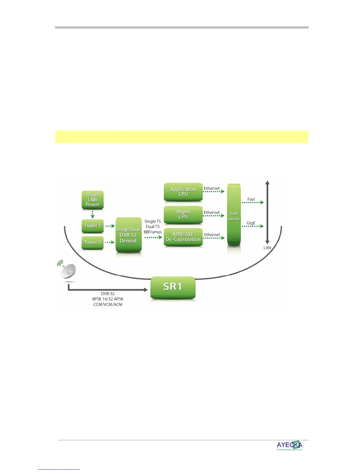
The SR1 Block Diagram is illustrated in Figure 2 SR1 Block Diagram
Figure 2 SR1 Block Diagram
The SR1 structure includes the following parts:
Tuner 1 and 2: Full L-Band RF front end with LNB powering and control. When SR1 operates
with a single demodulator, both tuners are assigned to the demodulator and the tuners act in
redundant mode. When using the SR1 in dual demodulator mode each demodulator has a
single tuner.
DVB-S2 Demodulator: The demodulator can be configured to a single demodulator (with the
support of up to 32APSK 45 MSPS VCM/ACM) or dual demodulator (with support of 8PCK
CCM 30Msps).
De-Capsulation: The De-Capsulation block extracts the IP/Ethernet packets from the
Transport stream (in MPE mode) or the Base Band Frames (in GSE mode). When SR1
operates with a single demodulator, all 8 De-Capsulation filters are assigned to the single
demodulator. When the SR1 operates in dual demodulator mode four filters are assigned to
each demodulator.