Advanced DVB-S2 Receiver Operational Manual
SR1 Specifications
16
5.3
Back Panel
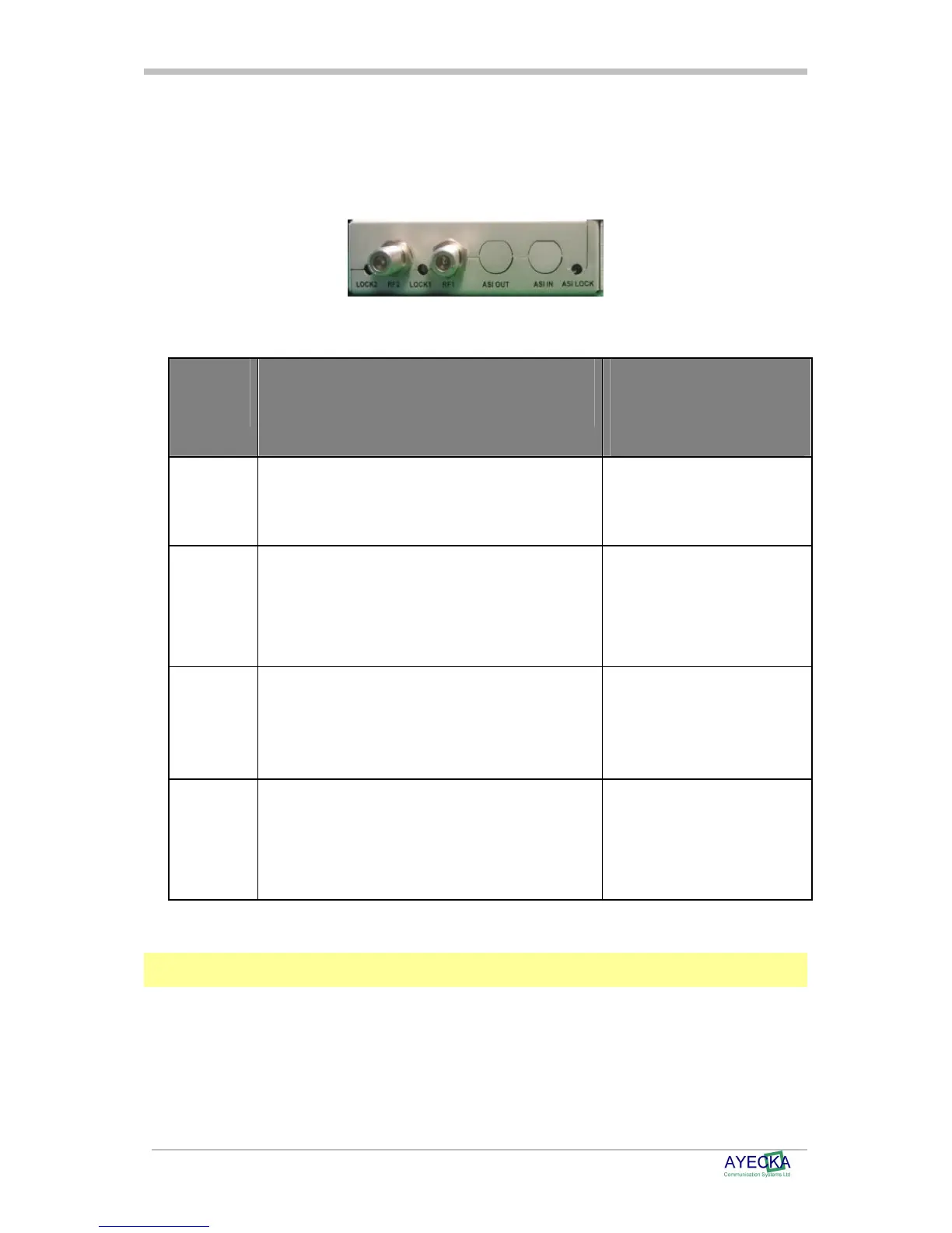
The SR1 Back panel containing the RF inputs is shown below:
Figure 4 - SR1 Back Panel
Table 3 - SR1 Back Panel Interfaces describes the back panel interfaces:
Interface
Description
Range
RF 1
DVB-S2 receiver RF input of receiver #1 F type Female Connector.
L-Band
-35 to -75 dBm
Lock 1
Status LED of #1 receiver RED : Receiver #1 is not
locked
Blinking RED :Receiver #1 is
in lock process
Green: Receiver #1 is locked
RF 2
DVB-S2 receiver RF input of receiver #2 F type Female Connector.
L-Band
-35 to -75 dBm
Lock 2
Status LED of #2 receiver RED: Receiver #2 is not
locked
Blinking RED: Receiver #2 is
in lock process
Green: Receiver #1 is locked
Table 3 - SR1 Back Panel Interfaces
Note
ASI out and ASI in are optional interfaces. For more information please contact Ayecka sales at
sales@ayecka.com.