12 Status and Operating Information
Operate the XS/SC26-2 Safety Controller using either the onboard interface or Software to monitor ongoing status.
Operate the SC10-2 Safety Controller using the Software to monitor ongoing status.
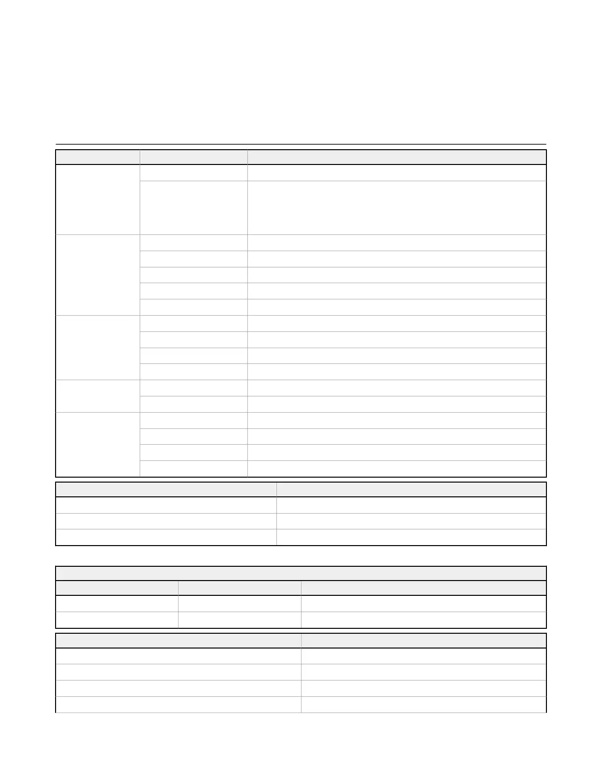
12.1 XS/SC26-2 LED Status
LED Status Meaning
All
Off Initialization Mode
Sequence:
Green On for 0.5 s
Red On for 0.5 s
Off for 0.5 s minimum
Power applied
Power/Fault
Off Power Off
Green: Solid Run mode
Green: Flashing Configuration or Manual Power-Up mode
Red: Flashing Non-operating Lockout condition
Red: Fast Flashing Safety Bus Communication Issue
USB
(Base Controller)
Off No link to the PC established
Green: Solid Link to the PC established
Green: Flashing for 5 s XM configuration match
Red: Flashing for 5 s XM configuration mismatch
Inputs
Green: Solid No input faults
Red: Flashing One or more inputs is in the Lockout condition
SO1, SO2
Off Output not configured
Green: Solid Safety Output On
Red: Solid Safety Output Off
Red: Flashing Safety Output fault detected or EDM fault detected or AVM fault detected
LED Status for Split Outputs Meaning
Green: Solid Both outputs are On
Red: Solid SO1 and/or SO2 Off
Red: Flashing SO1 and/or SO2 fault detected
Ethernet Diagnostic LEDs
Amber LED Green LED Description
On Varies with traffic Link established/normal operation
Off Off Hardware failure
Amber LED and Green LED Flash in Unison Description
5
flashes followed by several rapid flashes Normal power up
1 flash every 3 seconds Contact Banner Engineering
2 flash repeating sequence In the past 60 seconds, a cable was unplugged while active
3 flash repeating sequence A cable is unplugged
XS/SC26-2 and SC10-2 Safety Controllers
132 www.bannerengineering.com - Tel: + 1 888 373 6767
 Loading...


