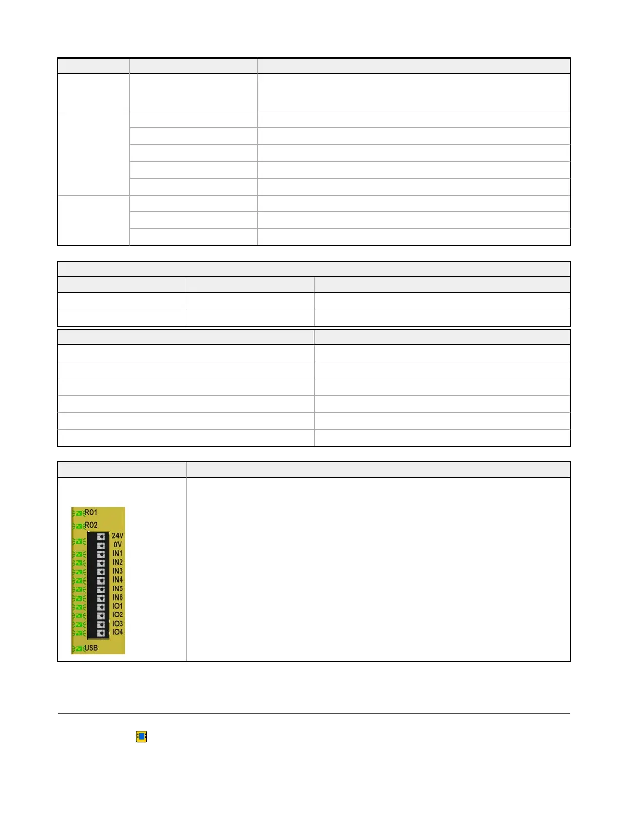
LED Status Meaning
Red: Flashing Configured (locked or unlocked) SC-XM3 plugged into a configured Safety Controller with a
mismatched configuration, a mismatched password, or a blank SC-XM3 plugged into any
Safety Controller
Inputs (10)
Green: Solid 24 V dc and no fault
Green: Solid Input configured as status output and active
Red: Solid 0 V dc and no fault
Red: Solid Input configured as status output and inactive
Red: Flashing All terminals of a faulted input (includes shared terminals)
RO1, RO2 (2)
Green: Solid On (contacts closed)
Red: Solid Off (contacts open) or not configured
Red: Flashing Safety Output fault detected or EDM fault detected or AVM fault detected
Ethernet Diagnostic LEDs
Amber LED Green LED Description
On Varies with traffic Link established/normal operation
Off Off Hardware failure
Amber LED and Green LED Flash in Unison Description
5
flashes followed by several rapid flashes Normal power up
1 flash every 3 seconds Contact Banner Engineering
2 flash repeating sequence In the past 60 seconds, a cable was unplugged while active
3 flash repeating sequence A cable is unplugged
4 flash repeating sequence Network not enabled in the configuration
5+ flash repeating sequence Contact Banner Engineering
PROFINET Flash Command Meaning
All LEDs
flash at a rate of twice per
second for 4 seconds
The flashing LEDs indicate that the SC10-2 is connected. It is the result of the "Flash LED" command from the
PROFINET network.
12.3 Live Mode Information: Software
To display real-time Run mode information on a PC, the Safety Controller must be connected to the computer via the SC-
USB2 cable. Click Live Mode to access the Live Mode tab. This feature continually updates and displays data, including
Run, Stop, and Fault states of all inputs and outputs, as well as the Fault Codes table. The Equipment tab and the
XS/SC26-2 and SC10-2 Safety Controllers
134 www.bannerengineering.com - Tel: + 1 888 373 6767
 Loading...


