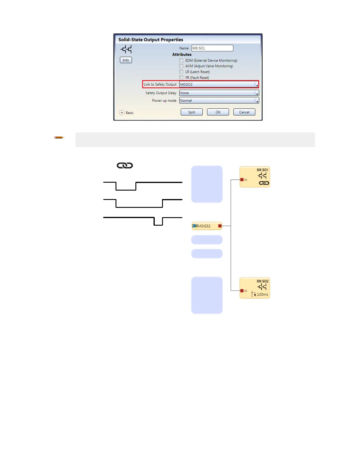
Figure 30. Example Link to Safety Output Selection
Note: The same input(s) need to be connected to both Safety Outputs in order for outputs to show
up as available for linking.
7. Click OK. The linked Safety Output will have a link icon indicator.
Figure 31. Timing Diagram—Linked Safety Outputs
7.8.1 XS/SC26-2 Solid-State Safety Outputs
The solid-state Safety Outputs, for example, SO1a and b, and SO2a and b, are actively monitored to detect short circuits to
the supply voltage, to each other, and to other voltage sources and are designed for Category 4 safety applications. If a
failure is detected on one channel of a safety output pair, both outputs attempt to turn Off and will enter a lockout state. The
output without the fault is able to turn off the hazardous motion.
Similarly, a Safety Output that is used individually (split), is also actively monitored to detect short circuits to other power
sources, but is unable to perform any actions. Take extreme care in the wiring of the terminals and in the routing of the
wires to avoid the possibility of shorts to other voltage sources, including other Safety Outputs. Each split Safety Output is
sufficient
for Category 3 applications due to an internal series connection of two switching devices, but an external short
must be prevented.
XS/SC26-2 and SC10-2 Safety Controllers
www.bannerengineering.com - Tel: + 1 888 373 6767 49