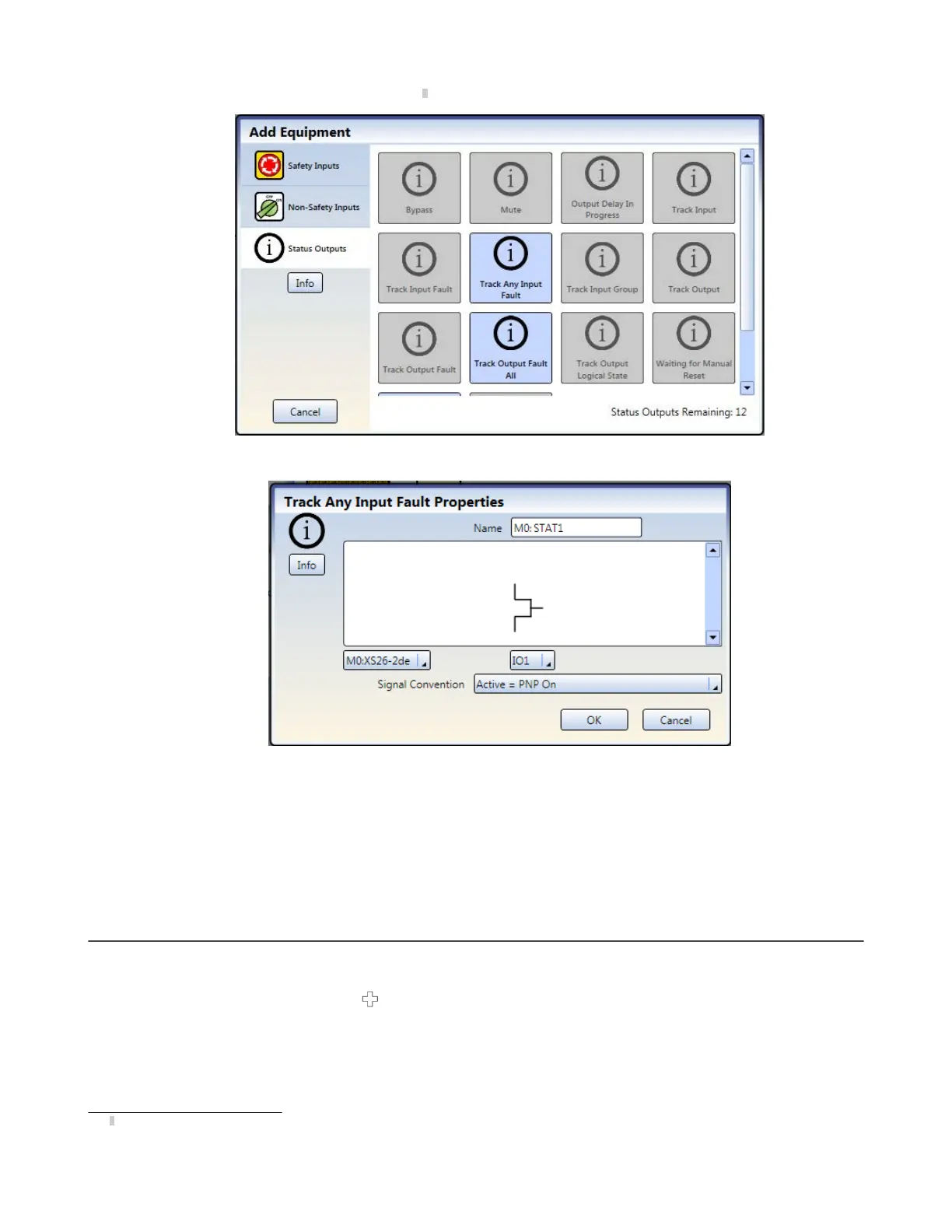
2. Click Status Outputs to add status monitoring
7
.
Figure 47. Status Outputs
3. Select appropriate Status Output settings:
Figure 48. Status Output Properties
•
Name
•
Module
•
I/O (where applicable)
•
Terminal
•
Input or Output (where applicable)
•
Signal Convention
8.3 Designing the Control Logic
To design the control logic:
1.
Add the desired Safety and Non-Safety Inputs:
• On the Equipment tab: click
under the module to which the input will be connected (the module can be
changed in the input Properties window)
• On the Functional View tab: click any of the empty placeholders in the left column
See
Adding Inputs and Status Outputs
on page 62 for more information and device properties.
2. Add Logic and/or Function Blocks (see
Logic Blocks
on page 78 and
Function Blocks
on page 80) by clicking
any of the empty placeholders in the middle area.
7
Status outputs can be configured when the state of an input device or an output needs to be communicated. The IOx terminals are used for these
status signals.
XS/SC26-2 and SC10-2 Safety Controllers
www.bannerengineering.com - Tel: + 1 888 373 6767 65