3. Select appropriate device settings:
Basic settings:
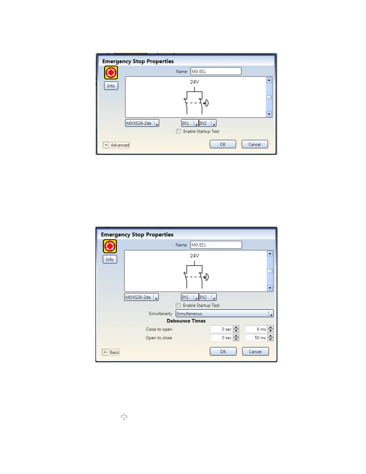
Figure 45. Basic Safety Input Settings
•
Name
—input device name; generated automatically and can be changed by the user
•
Circuit Type
—the circuit and signal convention options appropriate for the selected input device
•
Module
—the module to which the input device is connected
•
I/O Terminals
—the assignment of input terminals for the selected device on the selected module
•
Enable Startup Test
(where applicable)—an optional precautionary safety input device test required after
each power-up
•
Reset Options
(where applicable)—various reset options such as Manual Power Up, System Reset, and
Reset Track Input Group
Advanced settings (where applicable):
Figure 46. Advanced Safety Input Settings
•
Simultaneity
(where applicable)—Simultaneous or Concurrent (see
Glossary
on page 159 for definitions)
•
Debounce Times
—the signal state transition time
•
Monitored/Non-Monitored
(where applicable)
8.2.2 Adding Status Outputs
1.
On the Equipment tab, click below the module which will have the status monitoring.
XS/SC26-2 and SC10-2 Safety Controllers
64 www.bannerengineering.com - Tel: + 1 888 373 6767