EMC
Meets or exceeds all EMC requirements for immunity per IEC
61326-3-1:2012 and emissions per CISPR 11:2004 for Group 1, Class A
equipment
Note: Transient suppression is recommended when
switching inductive loads. Install suppressors
across load. Never install suppressors across
output contacts (see Warning).
Safety
Category 4, PL e (EN ISO 13849)
SIL CL 3 (IEC 62061, IEC 61508)
Safety Ratings
PFH [1/h]: 5.01 × 10
-10
Proof Test Interval: 20 years
Product Performance Standards
See
Standards and Regulations
on page 157 for a list of industry
applicable U.S. and international standards
Certifications
NRGF
PROGRAMMABLE
SAFETY
CONTROLLER
Required Overcurrent Protection
WARNING: Electrical connections must be
made by qualified personnel in accordance
with local and national electrical codes and
regulations.
Overcurrent protection is required to be provided by end product
application per the supplied table.
Overcurrent protection may be provided with external fusing or via
Current Limiting, Class 2 Power Supply.
Supply wiring leads < 24 AWG shall not be spliced.
For additional product support, go to
www.bannerengineering.com
.
Supply Wiring (AWG) Required Overcurrent Protection (Amps)
20 5.0
22 3.0
24 2.0
26 1.0
28 0.8
30 0.5
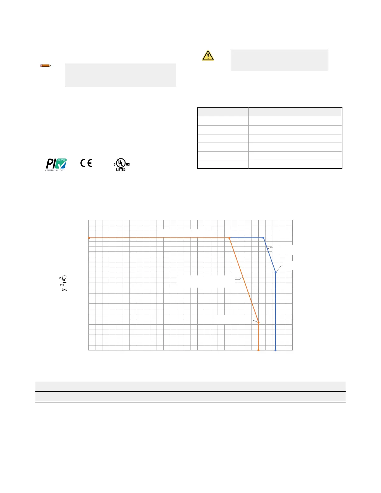
150
0
50
100
150
200
216
250
0 10 20 30 40 50 60
Sum of the squared current for each set of contacts
Temperature °C
SC10 Temperature Derating
3A/contact (54 A
2
)
5A/contact (150 A
2
)
6A/contact (216 A
2
)
Three modules side-by-side (no gap)
same load on each device
Single module
free standing
Example Temperature Derating Calculations
Single Unit, Free Standing Three Modules
∑I
2
= I
1
2
+ I
2
2
+ I
3
2
+ I
4
2
+ I
5
2
+ I
6
2
∑I
2
= I
1
2
+ I
2
2
+ I
3
2
+ I
4
2
+ I
5
2
+ I
6
2
(all six modules)
I
1
= 4 A (normally open output RO1 channel 1) I
1
= 4 A
I
2
= 4 A (normally open output RO1 channel 2) I
2
= 4 A
I
3
= 4 A (normally open output RO1 channel 3) I
3
= 4 A
I
4
= 4 A (normally open output RO2 channel 4) I
4
= 4 A
XS/SC26-2 and SC10-2 Safety Controllers
20 www.bannerengineering.com - Tel: + 1 888 373 6767
 Loading...


