Common Wire Installation
Consider the wire resistance of the 0 V common wire and the currents flowing in that wire to avoid nuisance lockouts.
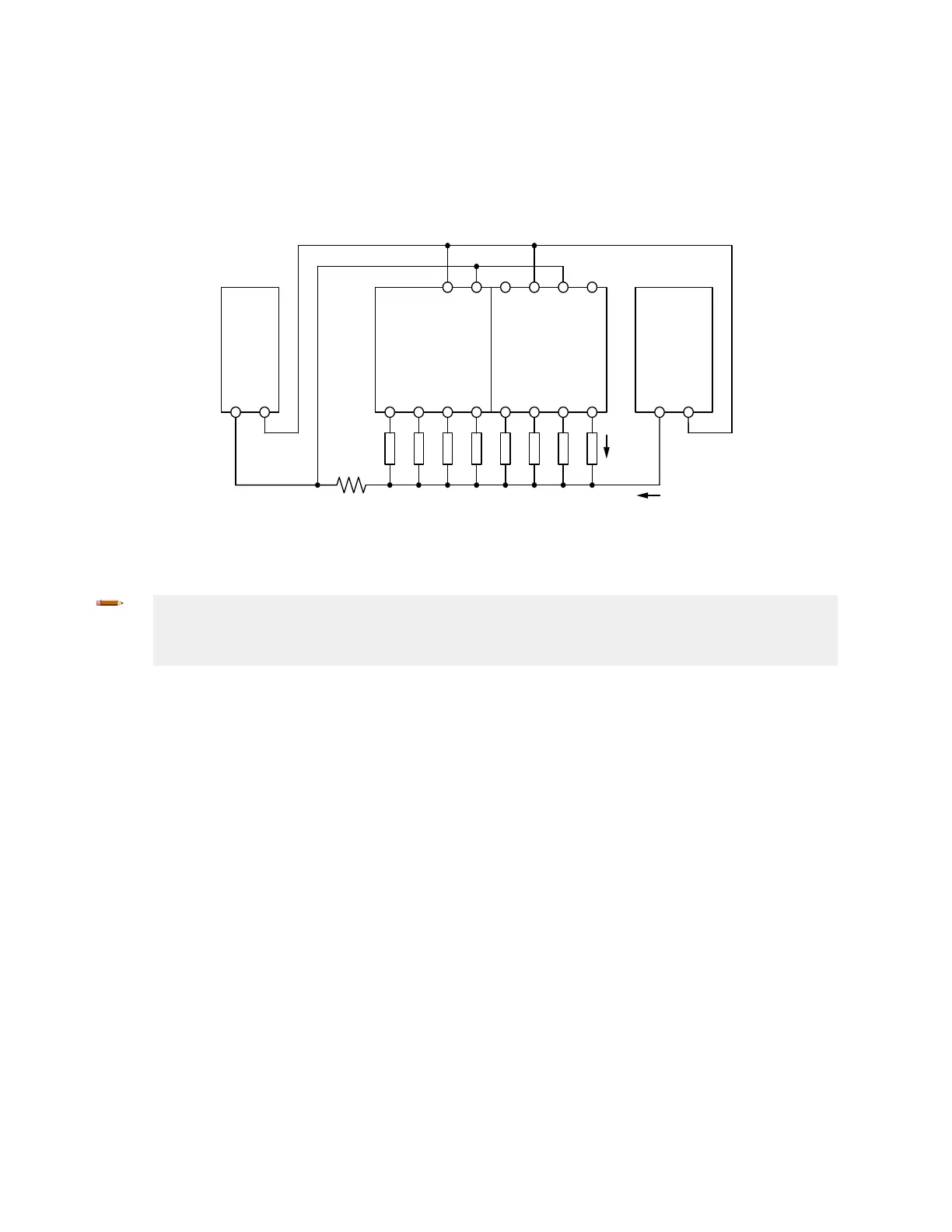
Notice the location of the resistance symbol in the diagram below representing 0 V common wire resistance (RL).
Methods to prevent this situation include:
•
Using larger gauge or shorter wires to reduce the resistance (R
L
) of the 0 V common wire
• Separate the 0 V common wire from the loads connected to the Safety Controller and the 0 V common wire from
other equipment powered by the common 24 V supply
XS2so
Solid State Safety
Output Module
XS26-2 Expandable
Safety Controller
Power
Supply
0V 24V
24V 0V24V 0V
R
L
= Common leadwire shared by multiple loads or systems
Sharing of small gauge leadwire can lead to faults on
solid
state outputs.
Load
current
Other current
R
L
Other
Equipment
0V 24V
Figure 32. Common Wire Installation
Note: When the Safety Output turns Off, the voltage at that output terminal must drop below 1.7 V with
respect to the 0 V terminal on that module. If the voltage is higher than 1.7 V, the Safety Controller will
decide that the output is still on, resulting in a lockout. Consider using larger gauge wires, shorter wires, or
using a single point grounding scheme similar to what is shown in the following diagrams.
XS/SC26-2 and SC10-2 Safety Controllers
www.bannerengineering.com - Tel: + 1 888 373 6767 51
 Loading...


