Lockout/Tagout
Hazardous energy (lockout/tagout) must be controlled in machine maintenance and servicing situations in which the
unexpected energization, start up, or release of stored energy could cause injury. Refer to OSHA 29CFR 1910.147, ANSI
2244.1, ISO 14118 , ISO 12100 or other relevant standards to ensure that bypassing a safeguarding device does not
conflict
with the requirements that are contained within the standards.
WARNING: Limit Use of Bypass Function
The Bypass function is not intended for production purposes; it is to be used only for temporary or
intermittent actions, such as to clear the defined area of a safety light screen if material becomes "stuck".
When Bypass is used, it is the user's responsibility to install and use it according to relevant standards
(such as ANSI NFPA79 or IEC/EN60204-1).
Safe Working Procedures and Training
Safe work procedures provide the means for individuals to control exposure to hazards through the use of written
procedures for specific tasks and the associated hazards. The user must also address the possibility that an individual
could bypass the safeguarding device and then either fail to reinstate the safeguarding or fail to notify other personnel of the
bypassed condition of the safeguarding device; both cases could result in an unsafe condition. One possible method to
prevent this is to develop a safe work procedure and ensure personnel are trained and correctly follow the procedure.
Delay Block (XS/SC26-2 FID 2 Only and SC10-2)
The Delay Block allows a user-configurable ON or OFF delay of a maximum of 5 minutes, in 1 ms increments.
Default Nodes Additional Nodes Notes
IN -
Depending on the selection, a signal/state transition on the input node
will be delayed by the output delay time by either holding the output
OFF (ON Delay) or holding the output ON (OFF Delay) after a signal
transition.
Note: The actual delay time of a delay function block or a safety output with a delay can be up to 1 scan
time longer than the delay setting. Multiple delay blocks or delay outputs in series will increase the final
delay time by up to 1 scan for each delay function. For example, three 100 ms off delay function blocks in
series and a scan time of 15 ms may result in an actual delay time of up to 345 ms (300 ms + 45 ms).
The Cancel Delay Node is a configurable node if Off Delay is selected.
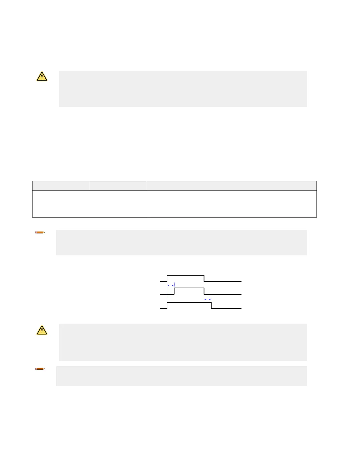
IN Node
Output Node - On Delay
Output Node - Off Delay
OFF Delay
ON Delay
Figure 59. Delay Block Timing Diagram
CAUTION: Delay time effect on response time
The off delay time may significantly increase the safety control response time. This will impact the
positioning of safeguards whose installation is determined by the safety (minimum) distance formulas or
are otherwise influenced by the amount of time to reach a non-hazardous state. The installation of
safeguards must account for the increase in response time.
Note: The response time provided on the
Configuration Summary tab is a maximum time that can change
depending on the use of delay blocks and other logic blocks (such as OR functions). It is the user’s
responsibility to determine, verify, and incorporate the appropriate response time.
XS/SC26-2 and SC10-2 Safety Controllers
www.bannerengineering.com - Tel: + 1 888 373 6767 81
 Loading...


