Enabling Device Block
Default Nodes Additional Nodes Notes
ED
IN
RST
ES
JOG
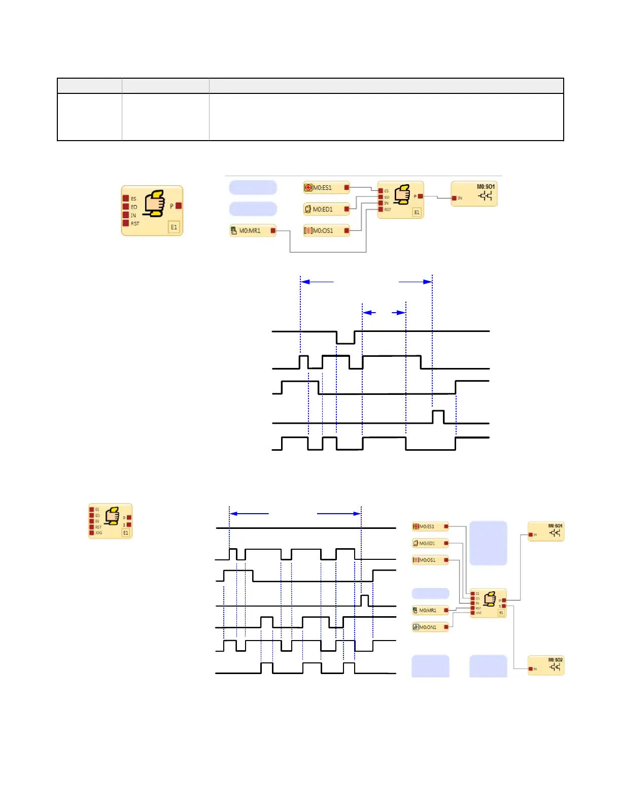
An Enabling Device Block must be connected directly to an Output Block. This method assures that the
final control of the outputs is given to the operator holding the Enabling Device. Use the ES node for
safety signals that should not be bypassed by the ED node. If no other inputs of the function block are
configured, using an Enabling Device function block is not required.
t
limit
M0:SO1
M0:ES1
M0:ED1
M0:OS1
M0:MR1
Enable Mode
ES1 &
ED1 have On/Off Control
Enabling Device
Function Block
Figure 61. Timing Diagram—Enabling Device, Simple Configuration
E1 enabling mode starts when the Enabling Device ED1 is switched to the Run state.
ED1 and ES input devices have On/Off control authority while in Enable mode.
When MR1 is used to perform a reset, the normal Run mode is re-established and OS1
and ES1 have the On/Off control authority.
Enabling Device Primary &
Secondary Output Control
Enable Mode
M0:ON1
M0:SO1
M0:SO2
M0:ES1
M0:ED1
M0:OS1
M0:MR1
Figure 62. Timing Diagram—Enabling Device
XS/SC26-2 and SC10-2 Safety Controllers
www.bannerengineering.com - Tel: + 1 888 373 6767 83
 Loading...


