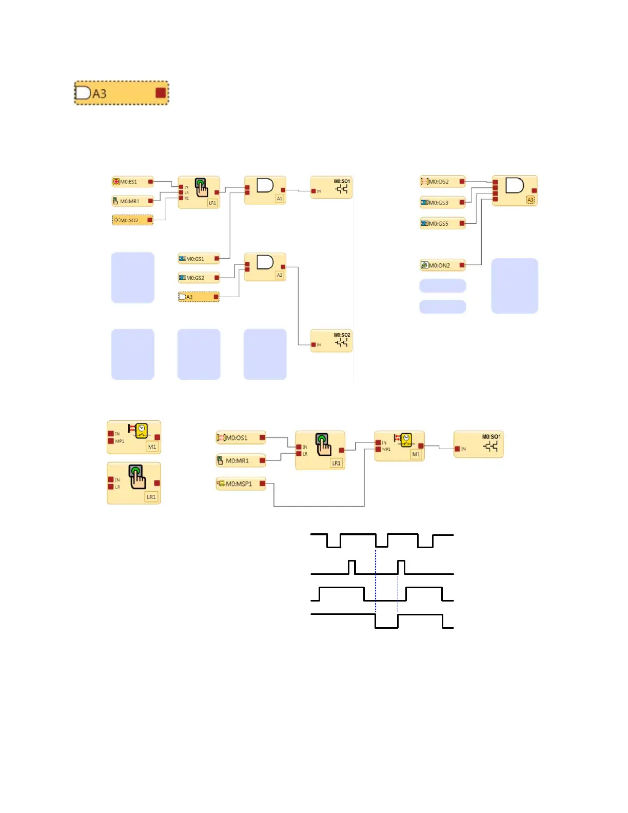
In the figure below, reference signal A3 is on page 1 of the function block diagram
and the A3 AND block is on page 2. The output node on the A3 AND block can also
be used on page 2 for other safety control logic.
Reference Signals
Reference signal A3 on page 1 AND logic block A3 on page 2
Figure 66. Latch Reset and Referenced Safety Output and AND block
When a safeguarding device OS1 transitions to a Stop state in a valid muting cycle, the
latch reset function block will latch and require a reset signal to keep SO1 on after
muting ends.
If OS1 switches to the Stop state in a valid muting cycle and no reset signal is seen,
SO1 turns off after muting ends.
M0:OS1
M0:MR1
M0:MSP1
M0:SO1
Latch Reset
Mute Function
Figure 67. Timing Diagram—Latch Reset Block and Muting Block
XS/SC26-2 and SC10-2 Safety Controllers
www.bannerengineering.com - Tel: + 1 888 373 6767 87
 Loading...


