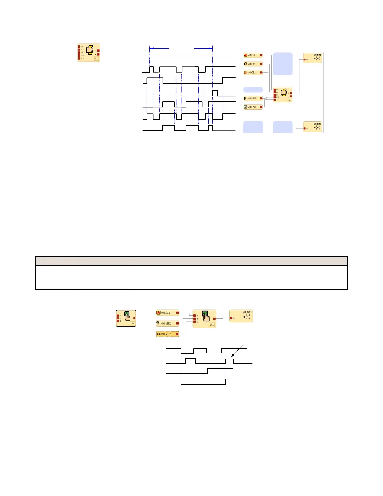
E1 enabling mode starts when the Enabling Device ED1 is switched to the Run state.
ED1 and ES input devices have On/Off control authority while in Enable mode.
When MR1 is used to perform a reset, the normal Run mode is re-established and OS1 and ES1
have the On/Off control authority.
Enabling Device Primary &
Secondary Output Control
Enable Mode
M0:ON1
M0:SO1
M0:SO2
M0:ES1
M0:ED1
M0:OS1
M0:MR1
Figure 18. Timing Diagram—Enabling Device
To exit the Enable mode, the enabling device must be in the Off state, and an Enabling Device Block reset must be
performed.
The enabling device time limit may be adjusted between 1 second and 30 minutes and cannot be disabled. When the
time limit expires, the associated safety outputs turn Off. To start a new Enable mode cycle, with the time limit reset to its
original value, the enabling device must switch from On to Off, and then back to On.
All On- and Off-delay time limits associated with the safety outputs that are controlled by the enabling device function are
followed during the Enable mode.
Latch Reset Block
Default Nodes
Additional Nodes Notes
IN
LR
RE
The RE (Reset Enable) node can be used to enable or disable the Latch Reset function. If the input
devices connected to the IN node are all in the Run state and RE input signal is high, the LR function
block can be manually reset to have its output turn On. See Figure 19 on page 28 with Reference Signal
SO2 connected to the RE node.
The Latch Reset function block LR1 will turn its output and the safety output SO1 Off when the
E-Stop button changes to the Stop state.
The latch off condition can be reset when the Reset Enable RE of LR1 detects that the SO2 refer-
ence signal is in the Run state & MR1 is used to perform a reset.
Latch Reset
Function Block
Non Monitored
Reset Signal
M0:ES1
M0:MR1
M0:SO2
M0:SO1
Figure 19. Timing Diagram—Latch Reset Block
XS/SC26-2 Safety Controller
28