6. Adjustments with the ADVANCED menu
2. Select EDGE BLEN D IN G by pressing the ▲ or ▼ key.
EDGE BLENDING
OFF
Image 6-11
3. Select ON by pressing the ◄ or ► key.
4. Select SETTING by pressing the ▲ or ▼ key.
SETTING
EDGE ADJUST
Image 6-12
5. Select EDGE AD JUST by pressing the ◄ or ► key.
0
128
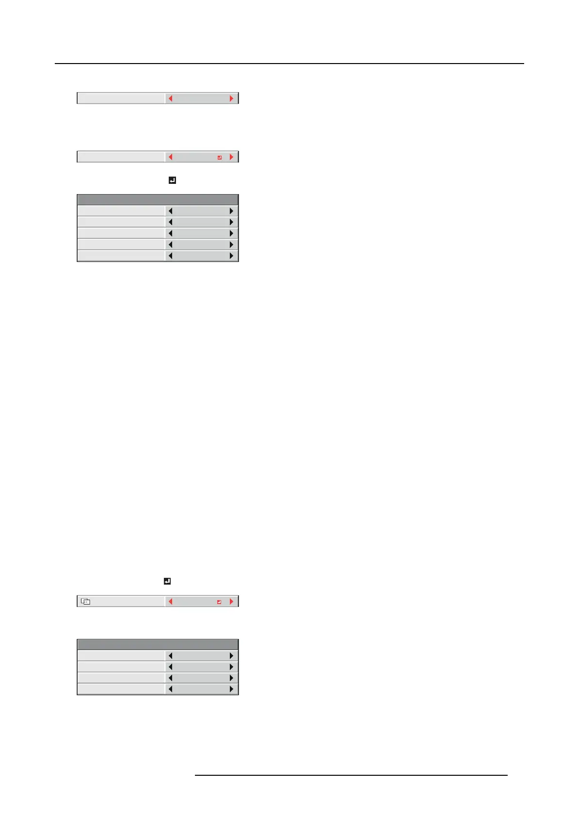
SETTING - EDGE ADJUST
EDGE SELECT
BLENDING
WIDTH
MARKER
UP
OFF
OFF
START POSITION
Image 6-13
6. Press the ENTER key.
7. Select an item you want to set by pressing the ▲ or ▼ key.
EDGE SELECT Select the joint you w ant to adjust from UP, LOW, LEFT, a nd RIGHT.
BLENDING W hen y ou select ON, the joint selected by E DG E SE LECT be come s unnoticeable.
STA RT
POSITION
Set the position to s tart th e edge adjustment.
When UP or LOW is selected:
• 0 to 270 (for P HW U-81B)
• 0 to 192 (for PHWX-81B/PHX G-91B)
When LEFT or RIGHT is selected:
• 0 to 480 (for P HW U-81B)
• 0 to 256 (for PHWX-81B/PHX G-91B)
WIDTH Set the width of the overlap of the joint selected by EDGE SELE CT.
When UP or LOW is selected:
• 4 to 524 (for P HW U-81B)
• 4 to 368 (for PHWX-81B/PHX G-91B)
When LEFT or RIGHT is selected:
• 4 to 944 (for P HW U-81B)
• 4 to 496 (for PHWX-81B/PHX G-91B)
The setting range of START POSITION and W IDTH vary depending on their s etting values.
MARKER When yo u select ON, a marker for easily locating the overlap of the joint is displayed.
8. Select a setting value by pressing the ◄ or ► key.
9. Repeat step 7 and step 8, if ne cessary.
10.Press the MENU k ey once.
11.Select BLACK LEVEL
by pressing the ◄ or ► ke y.
SETTING
BLACK LEVEL
Image 6-14
12.Press the ENTER key.
0
0
0
SETTING - BLACK LEVEL
INTERLOCKED
RED
GREEN
ON
BLUE
Image 6-15
13.Select an item you want to set by pressing the ▲ or ▼ key.
→ Adjust the black level in areas other than the overlapped areas.
→ W hen you set IN TERLO CKE D to ON, you can adjust RED, GREEN, and BLUE simultaneously. Whe n you set it to O FF, you
can adjust RED, GREEN, and BLUE separately.
R5905597 PHXX SERIES 20/05/2014 65
 Loading...