Specifications, Requirements, and Precautions
16 Basler pilot
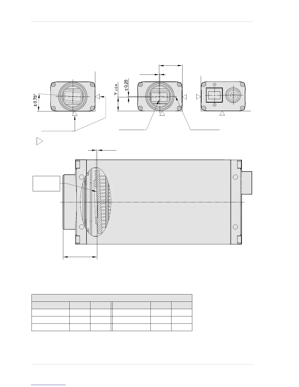
1.5.1.2 Sensor Positioning Accuracy
The sensor positioning accuracy is as shown in the drawings below.
Fig. 12: Sensor Positioning Accuracy (in mm Unless Otherwise Noted)
= reference plane
To the length
of the housing
± 0.25
X
± 0.4
Center lines
of the sensor
Center lines
of the thread
17.5
+ 0
0.06
-
Photosensitive
surface of the
sensor
± 0.02
(This is the sensor tilt tolerance. It applies to every point on the
photosensitive surface and is relative to the center of the die.)
( 2 : 1 )
(This tolerance is for the distance between the front of the
lens mount and the sensor’s photosensitive surface.
Note that this tolerance and the sensor tilt tolerance (see
above) must be combined to obtain the total tolerance for
every point on the photosensitive surface.)
Maximum Sensor Tilt Angle (Degrees)
Camera Tilt X Tilt Y Camera Tilt X Tilt Y
piA640-210gm/gc 0.48 0.63 piA1900-32gm/gc 0.16 0.29
piA1000-48gm/gc 0.31 0.31 piA2400-12gm/gc 0.27 0.32
piA1600-35gm/gc 0.19 0.26 piA2400-17gm/gc 0.27 0.32