Physical Interface
Basler pilot 73
7.7.2 Output Lines
7.7.2.1 Voltage Requirements
The following voltage requirements apply to the I/O output VCC (pin 10 of the 12-pin receptacle):
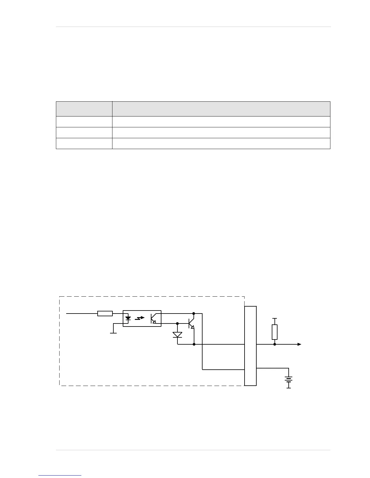
7.7.2.2 Line Schematic
The camera is equipped with four physical output lines designated as Output Line 1, Output Line 2,
Output Line 3, and Output Line 4. The output lines are accessed via the 12-pin receptacle on the
back of the camera.
As shown in the I/O schematic, each output line is opto-isolated. See the previous section for the
recommended operating voltage. The absolute maximum voltage is +30.0 VDC. The maximum
current allowed through an output circuit is 100 mA.
A conducting transistor means a logical one and a non-conducting transistor means a logical zero.
Figure 26 shows a typical circuit you can use to monitor an output line with a voltage signal. The
circuit in Figure 26 is monitoring output line 1.
Fig. 26: Typical Voltage Output Circuit
Voltage Significance
< +3.3 VDC The I/O output may operate erratically.
+3.3 to +24 VDC Recommended operating voltage.
+30.0 VDC Absolute maximum; the camera may be damaged if the absolute maximum is exceeded.
Table 9: Voltage Requirements for the I/O Output VCC