AR6201 - RT6201 - RCU6201 - AR6203
Page 2-12 DV 14307.03 Issue 1 09/2013
Note:
1. The sensitivity range of 1 mV to 20 mV was qualified under
environmental conditions. For installations with high interferences it
is recommended to use sensitivity level 2 mV to 20 mV.
2. Note: It is highly recommended to mount the jacks isolated from
aircraft frame in order to avoid ground loops.
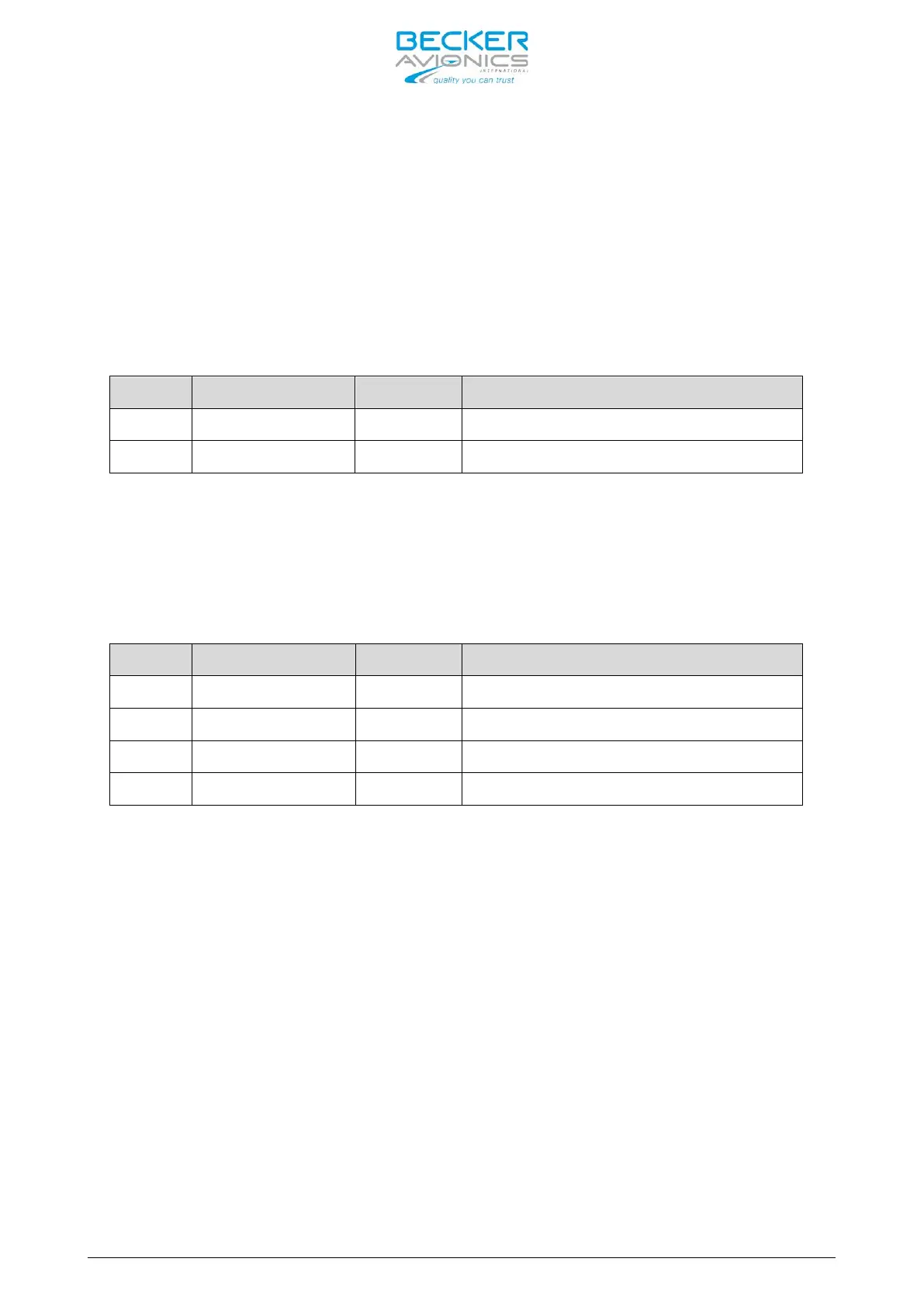
Speaker Connection
Pin No. Pin Name Direction Function
P1-1 SPK_HI OUT Speaker output signal
P1-14 SPK_LO - Speaker ground (return)
The speaker output provides nominal 4 W into 4 Ohm.
CAUTION: The magnetic field of a speaker influences the magnetic compass.
When choosing the mounting point, a safe distance between the
compass and the speaker must be determined. After speaker
installation, the accuracy of compass operation must be verified.
Headphone(s) Connection
Pin No. Pin Name Direction Function
P1-2 HDPH1_A OUT Balanced output for headphone(s) 1
P1-3 HDPH1_B OUT Balanced output for headphone(s) 1
P1-20 HDPH2_A OUT Balanced output for headphone(s) 2
P1-22 HDPH2_B OUT Balanced output for headphone(s) 2
The headphone 1 output is a balanced, transformer-coupled output providing
nominal 300 mW into 75 Ohm. For the use of a single shielded wire for
headphone a unbalanced output configuration is recommended. To achieve this
P1-3 can be grounded (connection to pin P1-13/P1-25).
The headphone 2 output is balanced output providing nominal 200 mW into 75
Ohm.
Up to two headphones with self-impedance of 300 Ohm (or higher) may be
connected in parallel on each circuit, therefore up to four headphones can be
connected at the same time.
Note: It is highly recommended to mount the jacks isolated from aircraft
frame in order to avoid ground loops.
CAUTION: The headphone 2 output shall be always floating (cannot be connected
in unbalance configuration as headphone 1).