EasyManuals Logo

Beckhoff EP31 Series User Manual

Beckhoff EP31 Series
149 pages
To Next Page IconTo Next Page
To Previous Page IconTo Previous Page
Page #42 background imageLoading...
Page #42 background image
Mounting and cabling
EP31xx42 Version: 2.4
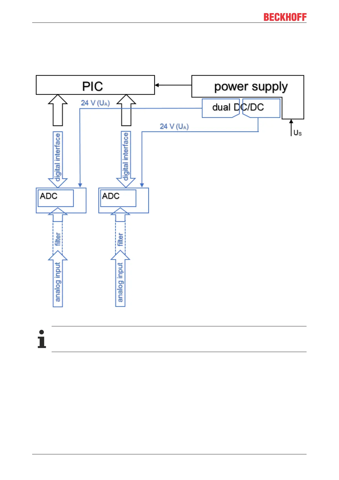
3.6 EP3162-0002 - Electrical isolation of the channels
The block diagram shown below illustrates the principle of the electrical isolation of the two channels. The
24V with which the channels are supplied come from an electrically isolated DC/DC and are thus U
A
instead
of U
S
.
Fig.21: Block diagram: electrical isolation
Electrical isolation of GND
The GNDs of channel 1 (GND
A
) and channel 2 (GND
B
) are electrically isolated from each other.

Table of Contents

Questions and Answers:

Question and Answer IconNeed help?

Do you have a question about the Beckhoff EP31 Series and is the answer not in the manual?

Beckhoff EP31 Series Specifications

General IconGeneral
BrandBeckhoff
ModelEP31 Series
CategoryControl Unit
LanguageEnglish