Configuration
EP31xx76 Version: 2.4
4.6 EP31xx - Settings and operating modes
4.6.1 Settings
Table of contents
• Selection of the analog signal type [}76]
• Representation [}77]
• Siemens bits [}77]
• Underrange, Overrange [}78]
• Limit 1 and Limit 2 [}78]
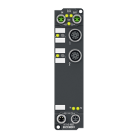
Selection of the analog signal type, index 0xF800:0n [
}
127]
In delivery state, all channels of the EP31xx are set for analog voltage measurement (-10V…+10V).
NOTE
Setting the correct signal type before connecting the sensors
Set the correct signal type before connecting the sensors!
This setting can be made individually for each channel in the CoE object 0xF800:0n [}127]. Changes are
immediately effective.
Fig.61: EP31x4-0002: Selection of the signal type
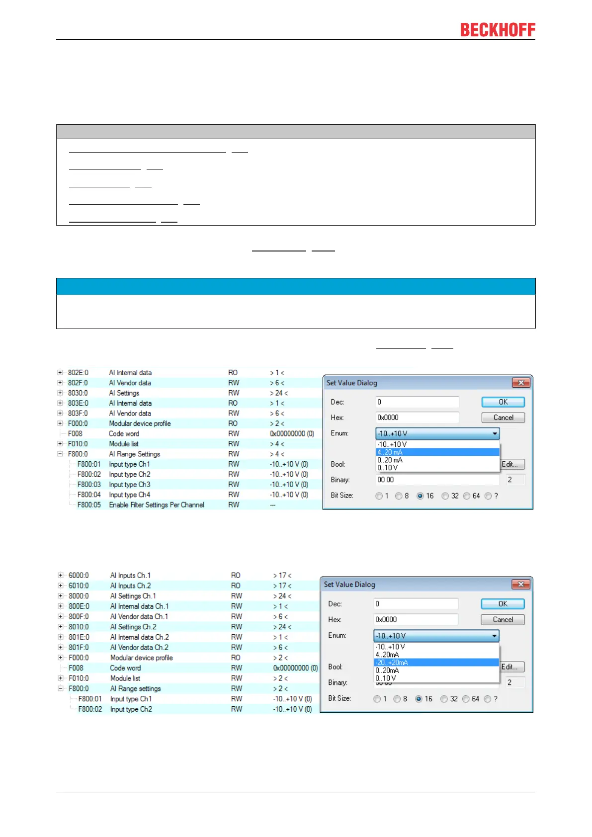
In the case of the EP31x2 the signal type -20mA to +20mA can additionally be selected (see illustration
below).
Fig.62: EP31x2: Selection of the signal type
 Loading...