Mounting and cabling
EP31xx 49Version: 2.4
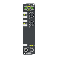
3.9.3 Status LEDs at the M12 connections
Fig.32: Status LEDs at the M12 connections
Connection LED Display Meaning
M12 socket no. 1-2 R
left
off Analog input: No data transfer to the A/D converter
green Analog input: Data transfer to A/D converter
red Error at the analog input: Broken wire or measured value outside
the measuring range
1
right
off Digital output switched off
green Digital output switched on
Function is without error if the left-hand LED is green.
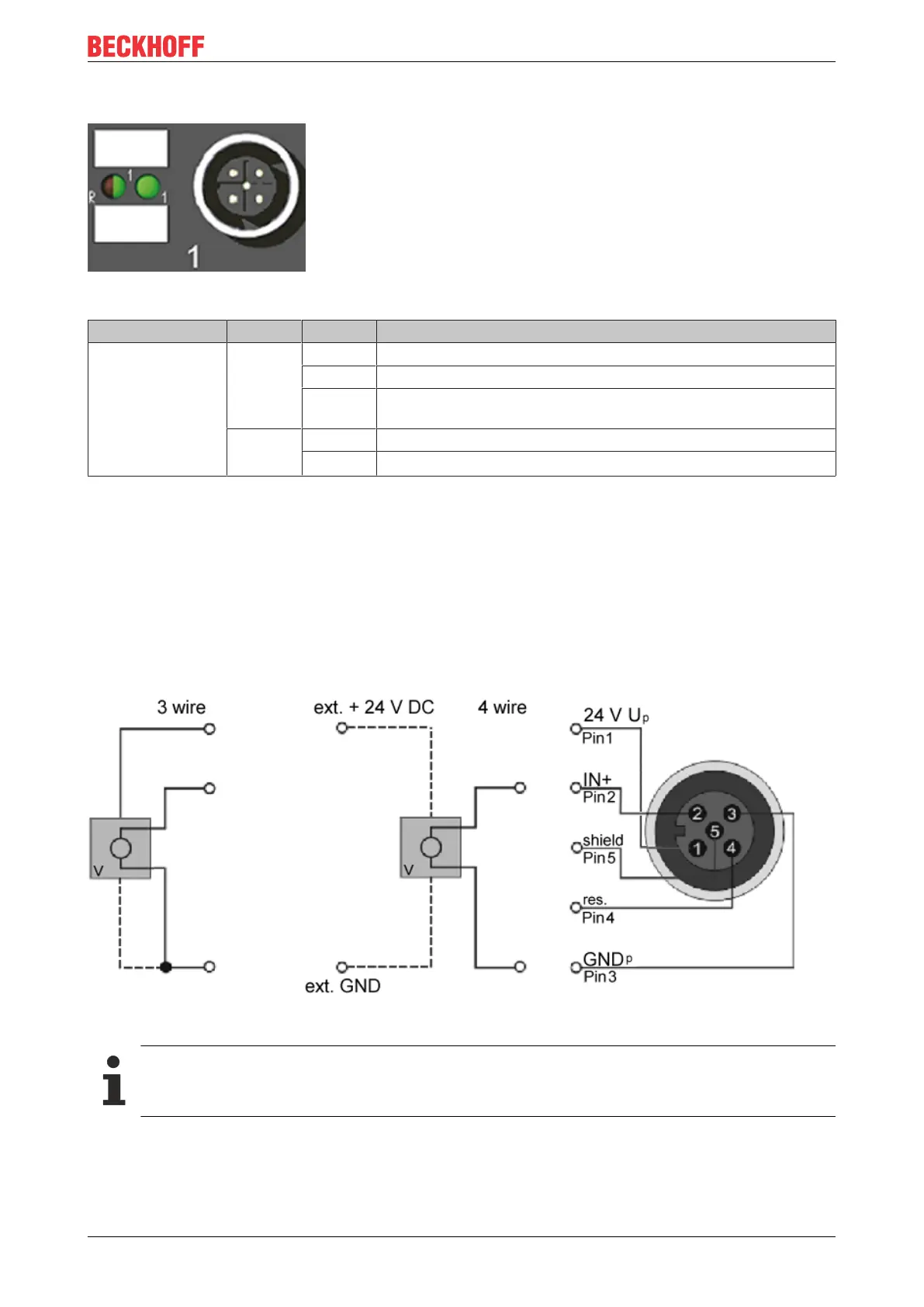
3.10 EP3184-0002 – Signal connection and Status LEDs
3.10.1 Analog voltage inputs M12, one single-ended input per socket
Analog input, -10V to +10V
Fig.33: Analog voltage inputs M12, one single-ended input per socket
GND connections
If several sensors are connected to a box whose GND connections are not electrically isolated,
GND must be connected to GNDp.
 Loading...