Mounting and cabling
EP31xx 51Version: 2.4
3.11 EP3184-1002 – Signal connection and Status LEDs
3.11.1 M12 analog voltage inputs, two single-ended inputs per socket
Analog inputs, -10V to +10V
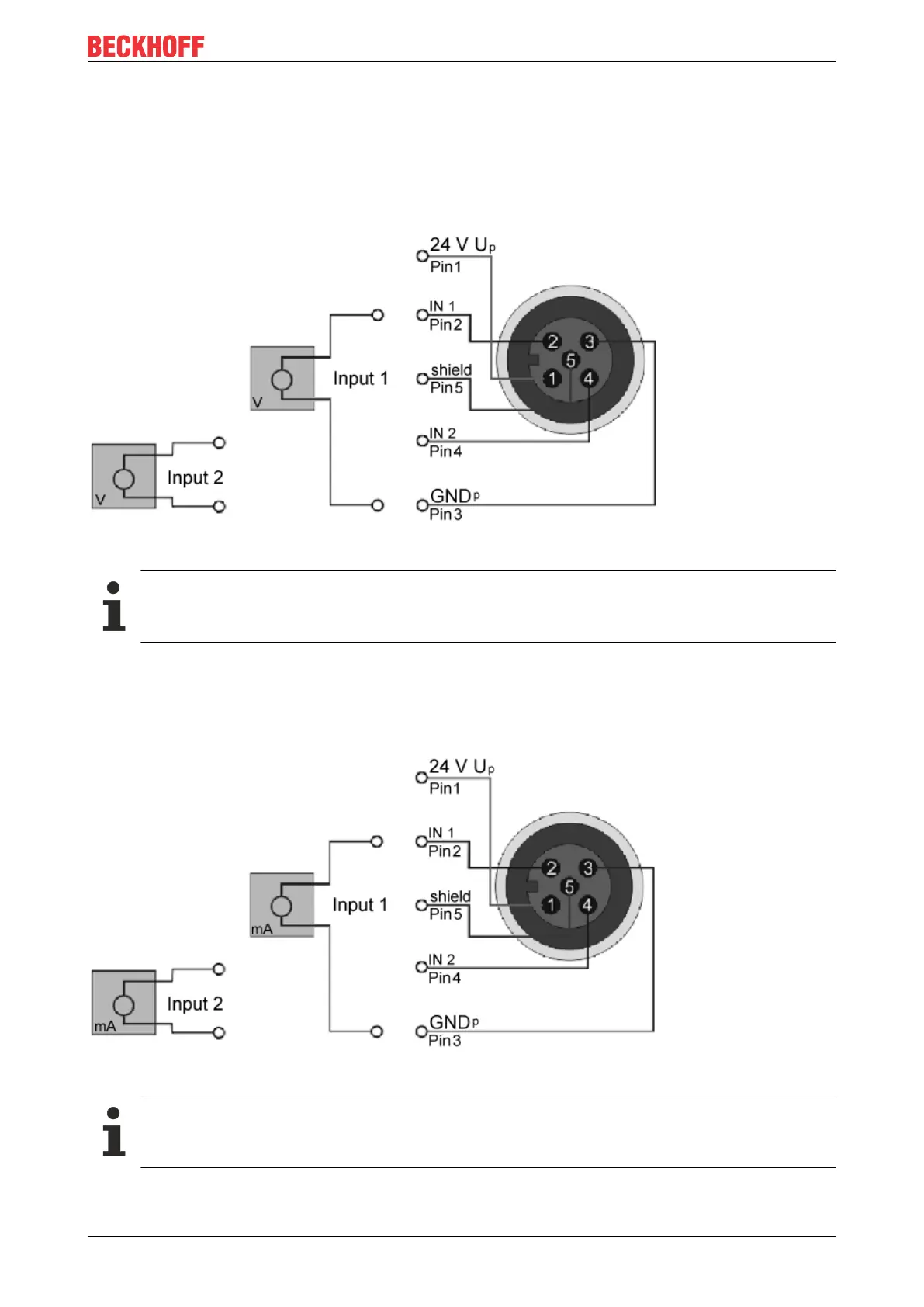
Fig.36: M12 analog voltage inputs, two single-ended inputs per socket
GND connections
If several sensors are connected to a box whose GND connections are not electrically isolated,
GND must be connected to GNDp.
3.11.2 M12 analog current inputs, two single-ended inputs per socket
Analog inputs, 0mA to 20mA or 4mA to 20mA
Fig.37: M12 analog current inputs, two single-ended inputs per socket
GND connections
If several sensors are connected to a box whose GND connections are not electrically isolated,
GND must be connected to GNDp.
 Loading...