Configuration
EP31xx74 Version: 2.4
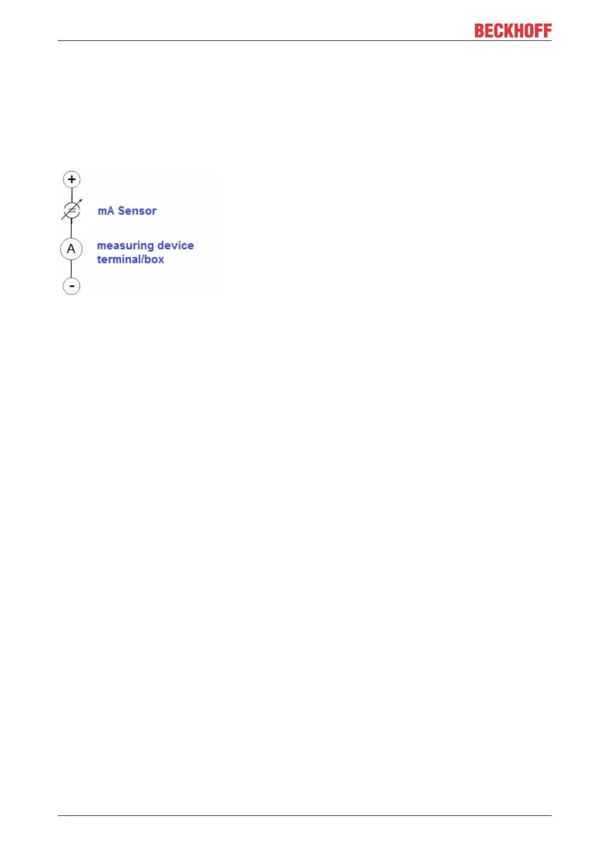
• Self-supplied sensors
◦ The sensor draws the energy for its own operation via the sensor/signal cable + and -. So that
enough energy is always available for the sensor’s own operation and open-circuit detection is
possible, a lower limit of 4mA has been specified for the 4-20mA interface; i.e. the sensor allows
a minimum current of 4mA and a maximum current of 20mA to pass.
◦ For a 2-wire connection; see IEC60381-1
◦ Such current transducers generally represent a current sink and thus like to sit between + and – as
a ‘variable load’. Refer also to the sensor manufacturer’s information.
Therefore, they are to be connected according to the Beckhoff terminology as follows:
• preferably to ‘single-ended’ inputs if the +Supply connections of the terminal/box are also to be used -
connect to +Supply and Signal
• the sensor draws the energy/operating voltage for its own operation from 2 supply cables of its own.
One or two further sensor cables are used for the signal transmission of the current loop:
Externally supplied sensors
• 3- and 4-wire connection see Fig. Connection of externally supplied sensors, cf. IEC60381-1
• the sensor draws the energy/operating voltage for its own operation from 2 supply cables of its
own. One or two further sensor cables are used for the signal transmission of the current loop:
1. sensor cable: according to the Beckhoff terminology such sensors are to be connected to ‘single-
ended’ inputs in 3 cables with +/-/Signal lines and if necessary FE/shield
2. sensor cables: In the case of sensors with 4-wire connection according to +-/+Signal/-Signal, you must
check whether +Signal may be connected to +Supply or –Signal to –Supply.
◦ Yes: then you can connect accordingly to a Beckhoff ‘single-ended’ input.
◦ the Beckhoff ‘differential’ input for +Signal and –Signal is to be selected; +Supply and –Supply
are to be connected via additional cables.
Notice: expert organizations such as NAMUR demand a usable measuring range <4mA/>20mA for error
detection and adjustment, see also NAMURNE043.
The Beckhoff device documentation must be consulted in order to see whether the respective device
supports such an extended signal range.
In general the polarity/direction of current is to be observed due to the internal diode!
 Loading...