Technical data IRDH575
106
IRDH575_D00089_05_M_XXEN/01.2020
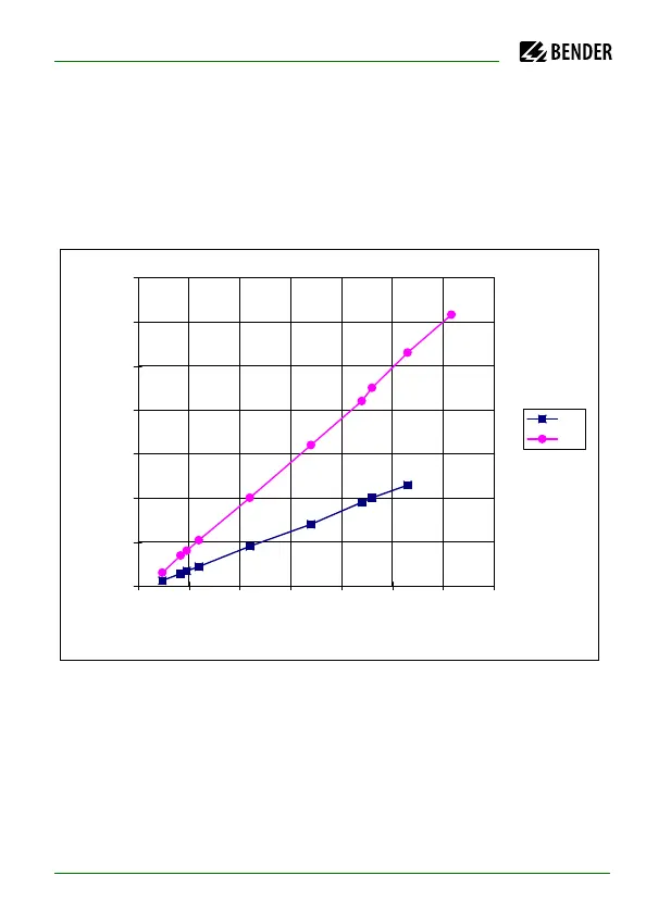
Limiting values for the insulation fault location system EDS473
In order to start automatic insulation fault location, the resistance values set
for ALARM 1 and ALARM 2 at a given nominal voltage must not be too high.
Otherwise, the EDS test current will not be sufficient for the detection of the
insulation fault. Determine the suitable values for your installation by means
of the characteristic curves
Curve 4:
Allowable response values in relation to the system voltage to be monitored
at a maximum system leakage capacitance C
e
as shown by curve 5.
DC: set a test current of 1 or 2.5 mA.
AC: set a test current of 2.5 mA.
The EDS473 system is suitable for nominal voltages of AC 265 V and DC 308 V.
0
100
200
300
400
500
600
700
0 50 100 150 200 250 300 350
U
n
(V)
R
F
(k)
AC
DC