Technical data IRDH575
105
IRDH575_D00089_05_M_XXEN/01.2020
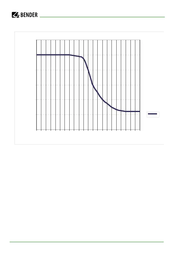
Curve 3:
A reduction of the response sensitivity at system leakage capacitances greater
than the maximum permissible value of C
e
taken from the curves 2a and 2b.
The indication of the test current on the IRDH575 display in case of high sys-
tem leakage capacitance also changes.
When considering the curves, a point to be taken into account is that the sum
of the pre-capacitances upstream the measuring current transformer must
amount to at least 50 % of the total capacitance. Otherwise it may result in
wrong alarm messages.
A value of 20 000µFV/400 V = 50µF is taken for the system leakage capaci-
tance. Exceeding the limiting value may result in false trippings.
0
20
40
60
80
100
120
x C
e
max
R
F
max
(%)
0,1 0,3 0,5 0,7 1,1 1,5 2,2 2,5 4 6 8
10