27
ENGLISH
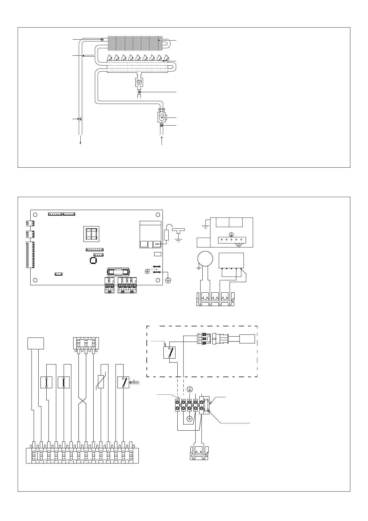
2.2 Water circuit
UAC
1
Maximum temperature thermostat
2
By-pass(Onlyformodels11-13ESI)
3
NTC probe
4
Exchanger
5
Burner
6
Gas valve
7
Flow switch
8
Filter
UAC
Hot water outlet
EAF
Domestic cold water inlet
Fig. 3
2.3 Multi-row wiring diagram
NOTE: L-N POLARISATION IS RECOMMENDED
E.A./R.
X2
X1
X4
TR2
X9
X8
X7
CN1
F1=2A
X5
X6
X3
TR1
IWH02
2
1
3
4
MOD
pk
OPE OPE
3 421
4
5
3
1
2
bl
V
br
br
bl
X2
1
gy
bk
bk
w
w
gy (OUT)
bl (+)
or (-)
r
r
pu
pu
MOD
T.B.
F.L.
-t°
S.S.
PAD
or (-)
gy (OUT)
bl (+)
1
3
T.L.
2
1
LN
230 V
F= 3.15A
M5
RFS
br
bl
bl
br
bk
bl
w
w
bl
bk
TAG
230 V
aux
(*)
IWH02
Control circuit diagram
CN1-X1-X9
Connectionttings
TR1
Transformer
TR2
Ignition transformer
F
External fuse 3.15A
F1
Fuse 2A
E.A./R.
Ignition/detection electrode
M5
Terminal board for external
connections:230V
V
Fan
VG
Gas valve
OPE
Gas valve operator
MOD
Modulator
T.B.
Burner thermostat
T.L.
Maximum temperature
thermostat
PAD
Analogue differential pres-
sure switch
S.S.
Domestic hot water circuit
temperatureprobe(NTC)
F.L.
Domestichotwaterow
switch
TAG (*)
Anti-freeze thermostat
RFS (*)
Heating wire resistor
pu
violet
r
red
bk
black
gy
grey
pk
pink
bl
blue
br
brown
w
white
or
orange
(*)
Only on models for outdoor
installation
Fig. 4
 Loading...