29
ENGLISH
B
E
C
A
A
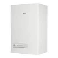
uegasespipe
B
suction line pipe
C
rubber rose
D
terminal
E
seat for rose
Fig. 9
- seal the gap between the 100 Ø pipe and the hole in the wall with ce-
ment-based mortar, positioning a piece of paper so that the tube does
not
remainxedtothewallitself,soastofacilitatesubsequentdisas-
sembly. Place the appliance in the chosen position, with reference to
the
measurements indicated in this instruction booklet in the “Func-
tional elements of the appliance / Max. dimensions and connections”
section.
3.3.2 Models for outdoor installation
The appliance has been designed only for installation outdoors in an area
that is partly covered. For this reason it must be installed in the open,
outdoors with natural aeration and ventilation, without stagnant zones for
combustion products, which should be rapidly dispersed by means of nat
-
ural convection or by the wind.
The discharge outlet of the appliance should be free of obstructions, ob-
jects
orbodiesthatcouldpreventitfromexpellingtheuegasescorrectly
and protected from an contacts during or after operation: it is possible it
overheats and cause burns.
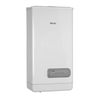
Fig. 10: example of an
INCORRECT
evacuation of the products of the
combustioninsideabalconyclosedonvesides.
Fig. 10
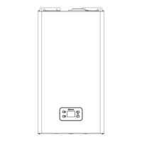
When the appliance is being installed the minimum distances of the dis-
charge/suction line must comply with current local legislation, having re-
gard for any other appliances installed, openings, architectonic elements,
and boundaries.
Positioning the terminal Position
Minimum distances
(mm) (*)
Appliances over
16kW up to 35kW
Under a window A1 600
Next to a window A2 400
Under an aeration/purging open-
ing
B1 600
Next to an aeration/purging
opening
B2 600
Verticaldistancebetweentwo
discharge terminals
C1 1.500
Horizontallyadjacenttoadis
-
charge terminal
C2 1.000
Under a balcony D1 300
Beside a balcony D2 1.000
From the ground or from another
walkway
E 2.200
From piping either vertical or
horizontaldischarges(**)
F 300
Under the eaves G 300
Corner/recess/wall of the building H 300
(*)
For type A appliances the minimum distance coincides with the cen-
tre of the outlet section for combustion products going into the air.
(**)
When positioning the appliance distances of not less than 500
mm must be adopted from materials sensitive to the action of the
combustion products (for example, plastic eaves and drainpipes,
protrudingwoodelements,etc.);forsmallerdistancesusesuitable
screening with regard to said materials.
Fig. 11
b
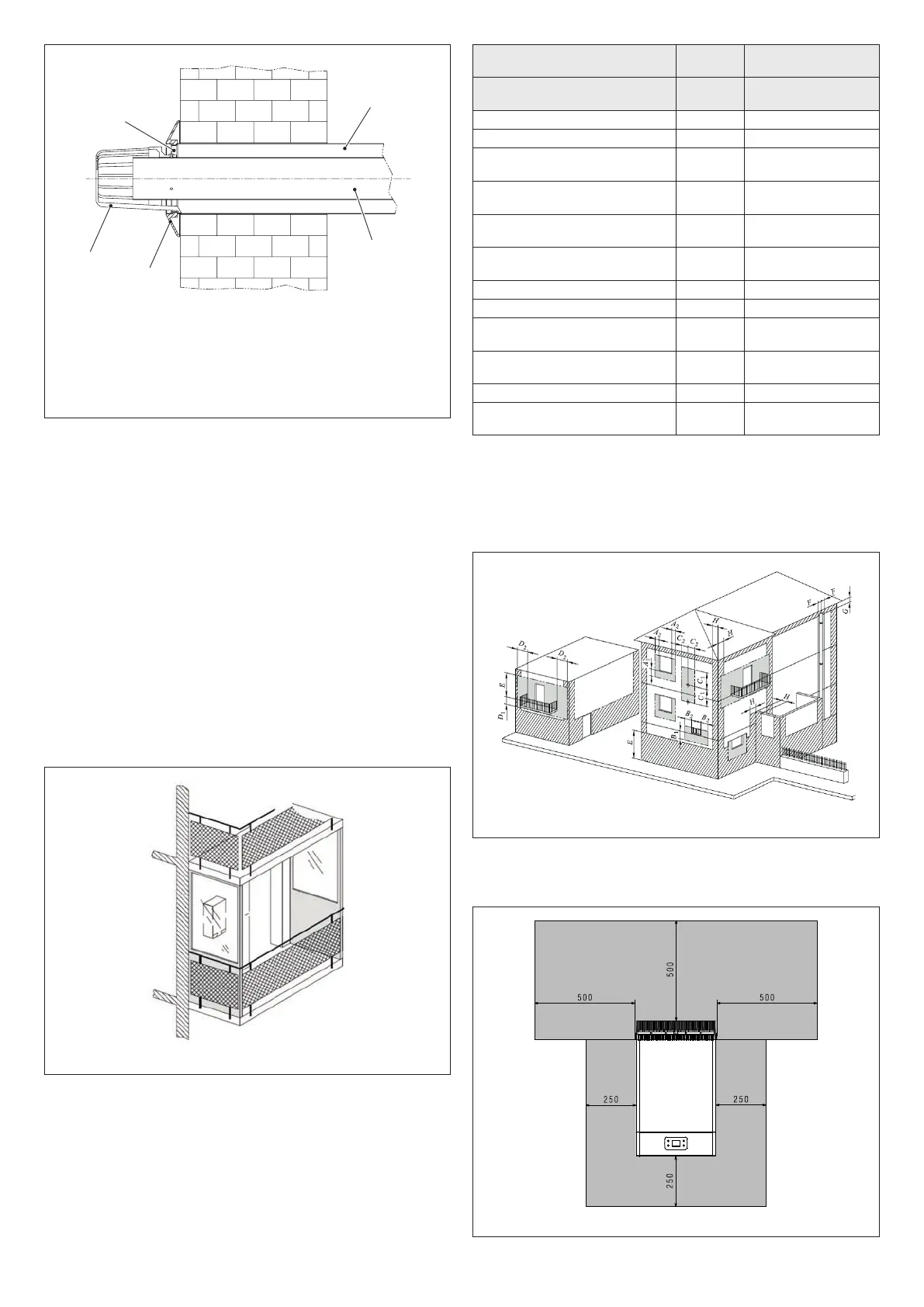
For the minimum distances from combustible materials, see what
is reported in Fig. 12
Fig. 12
 Loading...