30
ENGLISH
3.4 Evacuating products of combustion
3.4.1 Models for indoor installation
Foruegasdischarge,refertoStandardsUNI7129-7131.Theuegas
exhaust/air intake kit is not supplied with the boiler as accessories for
sealed-chamber forced-draught appliances, which better adapt to the in
-
stallation context, can be used.
T
o extract the ue gases and restore the combustion air in the boiler,
use original piping or others with the same characteristics which are EC
certiedandensurethattheyarecorrectlyconnectedasindicatedinthe
instructionsprovidedwiththeuegasesaccessories.
Asingleuecanbeconnectedtoseveralappliancesprovidedthatevery
appliance is sealed chamber type.
TheboilerisatypeCappliance(withasealedchamber)andmustthere
-
fore
haveasecureconnectiontotheuegasesexhaustpipeandcom-
bustion
air intake pipewhich both owoutside, and without which the
appliance cannot operate.
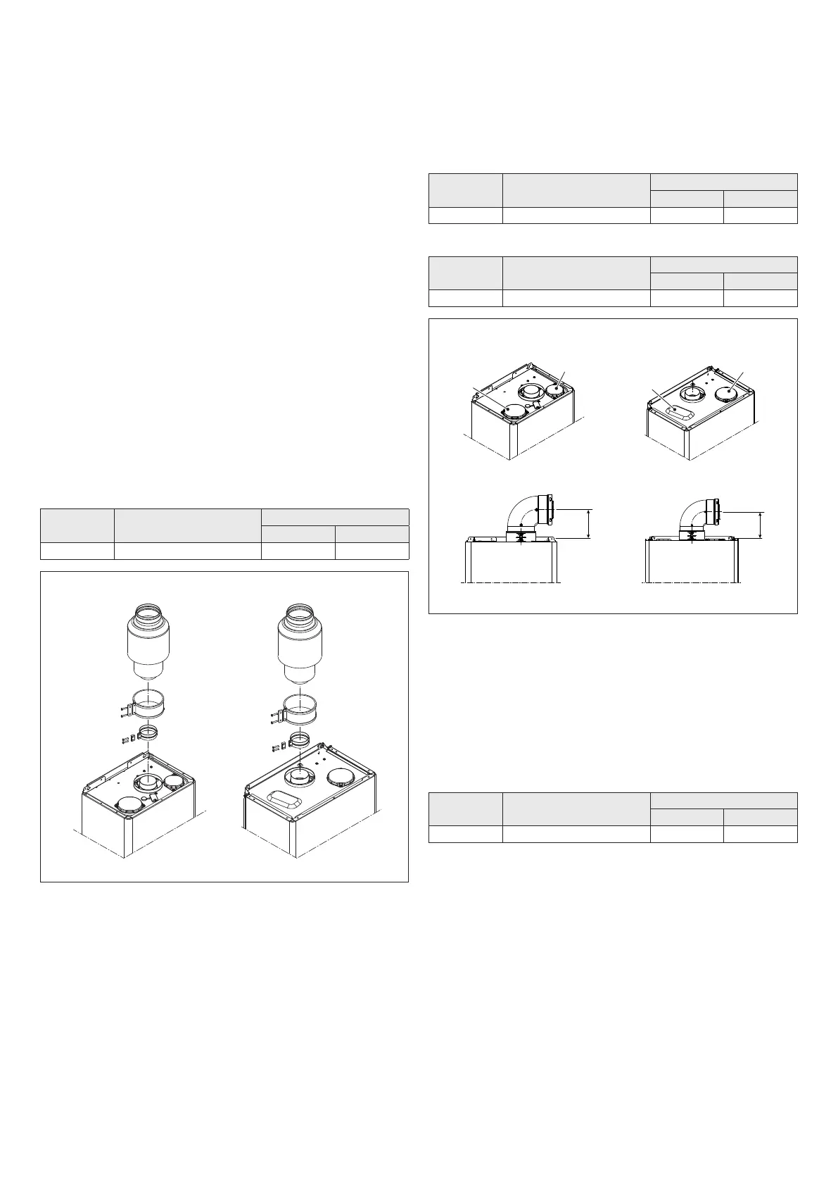
“FORCED OPEN” INSTALLATION (B22-B52)
Theuegasexhaustpipecanbedirectedtothemostsuitabledirection
according to installation requirements.
For installation, follow the instructions supplied with the kit.
Inthisconguration,theapplianceisconnectedtotheø80mmuegas
exhaustpipebymeansofaø60-80mmadaptor(Fig.13).
b
Inthiscongurationthecombustionairiswithdrawnfromtheroom
where the appliance is installed, which should be technically suita-
ble and ventilated.
b
The non insulated ue gas outlet pipes are potential sources of
danger.
b
The table indicates the permitted linear lengths.
Model
Maximum length
Ø 80 mm (m)
Loss of load (m)
45° bend 90° bend
11 - 13 15 1,2 1,7
Models 11-13 Models 17
Fig. 13
COAXIAL DISCHARGES (60-100 Ø)
The boiler has been designed to be connected to concentric discharge/
suction pipes and with the opening for air suction (
D
)closed(Fig.14).
Coaxialoutletscanbepointedinthedirectionmostsuitedtothespecic
installation room, in line with the lengths shown in the table.
For installation, follow the instructions supplied with the kit.
b
The table indicates the permitted linear lengths.
Horizontal
Model
Maximum length
Ø 60-100 mm (m)
Loss of load (m)
45° bend 90° bend
11 - 13 3,5 1 1,5
Vertical
Model
Maximum length
Ø 60-100 mm (m)
Loss of load (m)
45° bend 90° bend
11 - 13 4,5 1 1,5
Models 11-13 Models 17
112
117
D
D
Fig. 14
SPLIT PIPE OUTLETS (80 Ø)
Twin outlets can be placed in the most suitable direction according to the
room requirements.
The combustion air intake pipe must be chosen from the two inlets (
E
and
F
);removetheclosureplugxedwithscrewsandusethespecicadaptor
for the chosen input.
The air inlet adaptor Ø 80 (
E
)mustbeorientedcorrectly,soitmustbe
xedwiththerelativescrews,sothatthepositioningtabdoesnotinterfere
with the casing.
b
The table indicates the permitted linear lengths.
Model
Maximum length
Ø 80 mm (m)
Loss of load (m)
45° bend 90° bend
11 - 13 15+15 1,2 1,7
 Loading...