7
ITALIANO
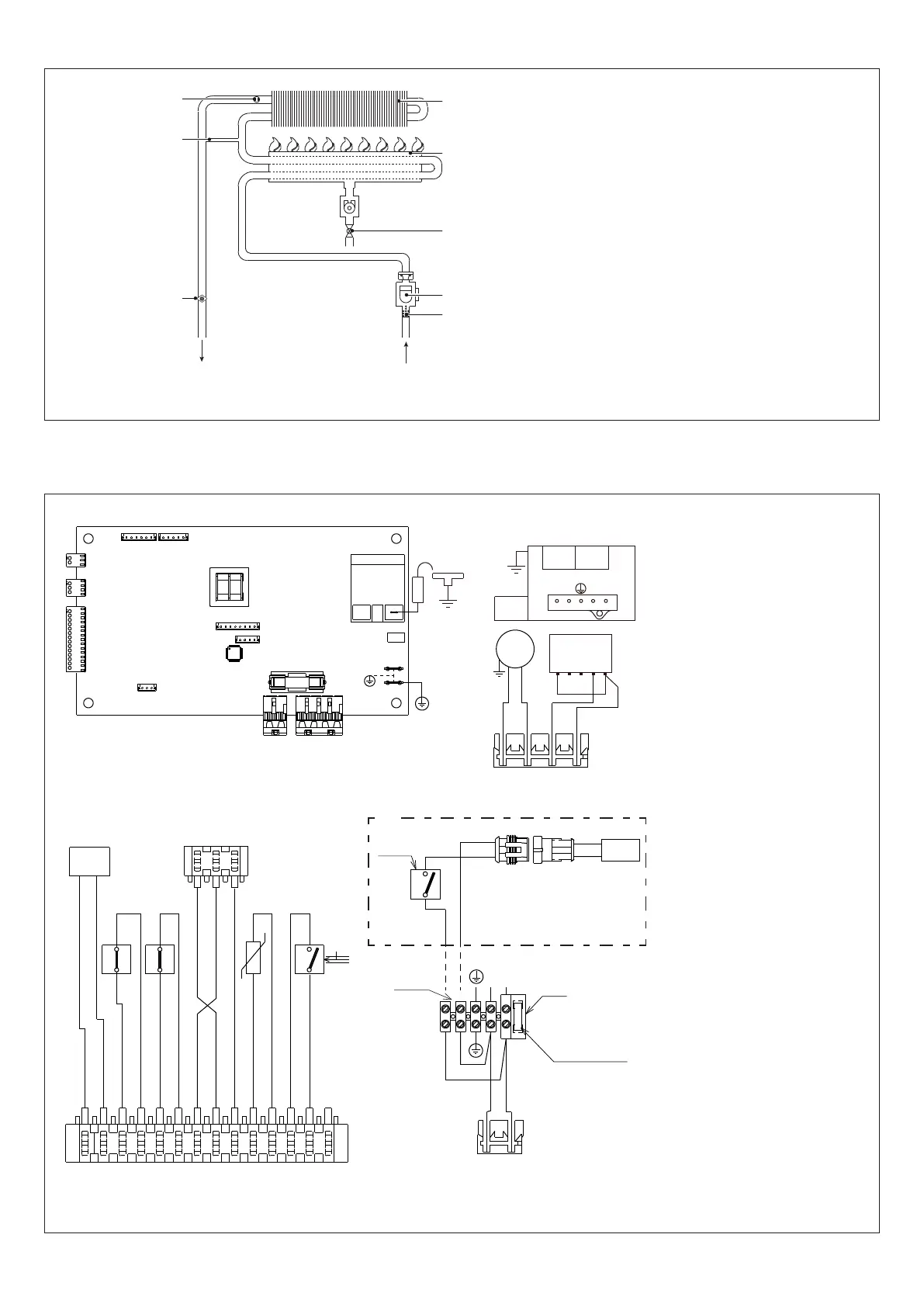
2.2 Circuito idraulico
UAC
1
Termostato limite
2
By-pass(Solopermodelli11-13ESI)
3
Sonda NTC
4
Scambiatore
5
Bruciatore
6
Valvolagas
7
Flussostato
8
Filtro
UAC
Uscita acqua calda
EAF
Entrata acqua fredda
Fig. 3
2.3 Schema elettrico multifilare
NOTA: LA POLARIZZAZIONE L-N È CONSIGLIATA
E.A./R.
X2
X1
X4
TR2
X9
X8
X7
CN1
F1=2A
X5
X6
X3
TR1
IWH02
2
1
3
4
MOD
pk
OPE OPE
3 421
4
5
3
1
2
bl
V
br
br
bl
X2
1
gy
bk
bk
w
w
gy (OUT)
bl (+)
or (-)
r
r
pu
pu
MOD
T.B.
F.L.
-t°
S.S.
PAD
or (-)
gy (OUT)
bl (+)
1
3
T.L.
2
1
LN
230 V
F= 3.15A
M5
RFS
br
bl
bl
br
bk
bl
w
w
bl
bk
TAG
230 V
aux
(*)
IWH02
Schema comando
CN1-X1-X9
Connettori di collega-
mento
TR1
Trasformatore
TR2
Trasformatore di accensio-
ne
F
Fusibile esterno 3.15A
F1
Fusibile 2A
E.A./R.
Elettrodo accensione/rile-
vazione
M5
Morsettiera per collega-
mentiesterni:230V
V
Ventilatore
VG
Valvolagas
OPE
Operatore valvola gas
MOD
Modulatore
T.B.
Termostato bruciatore
T.L.
Termostato limite
PAD
Pressostato analogico
differenziale
S.S.
Sonda(NTC)temperatura
circuito sanitario
F.L.
Flussostato sanitario
TAG (*)
Termostato antigelo
RFS (*)
Resistenza filo scaldante
pu
viola
r
rosso
bk
nero
gy
grigio
pk
rosa
bl
blu
br
marrone
w
bianco
or
arancione
(*)
Solo su modelli per installazio-
ne esterna
Fig. 4
 Loading...