67
ESPAÑOL
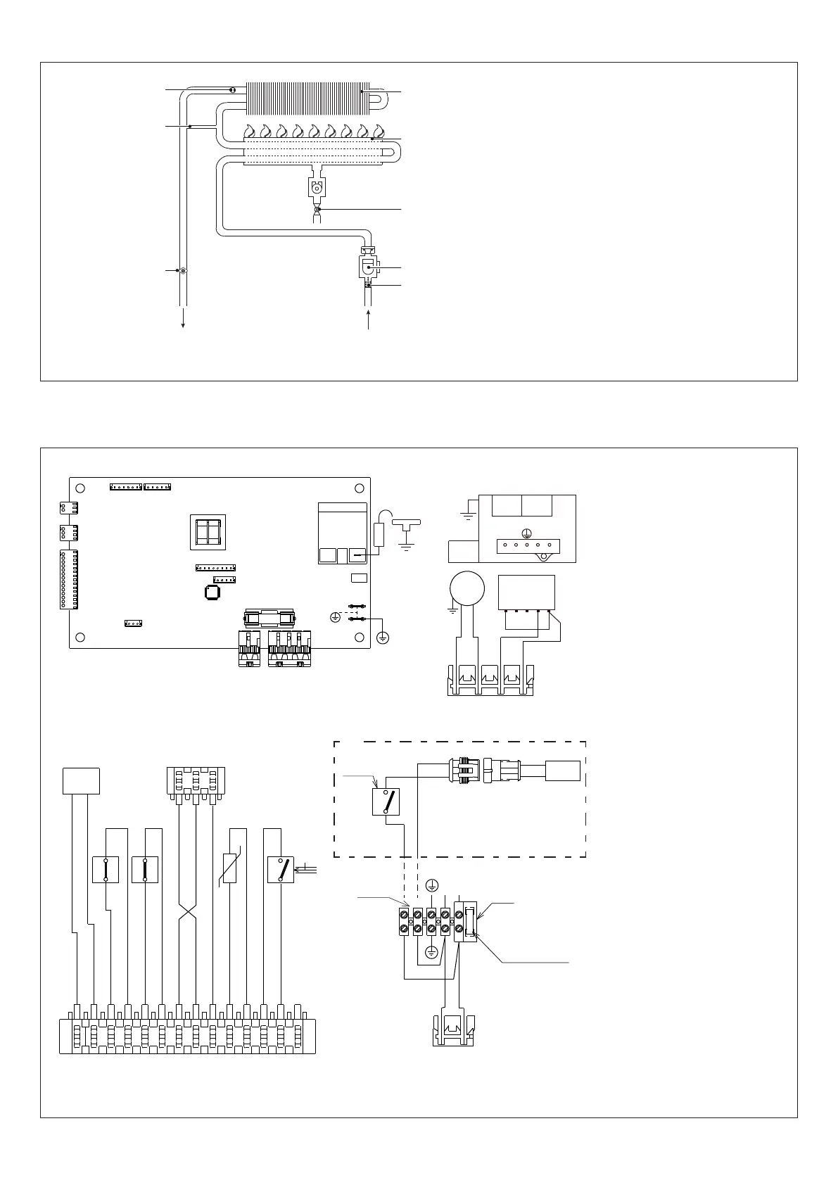
2.2 Circuito hidráulico
UAC
1
Termostato límite
2
By-pass(Soloparamodelos11-13ESI)
3
Sonda NTC
4
Intercambiador
5
Quemador
6
Válvulagas
7
Microinterruptordeujo
8
Filtro
UAC
Salida de agua caliente
EAF
Entrada de agua fría
Fig. 3
2.3 Esquema eléctrico multihilo
NOTA: SE RECOMIENDA LA POLARIZACIÓN L-N
E.A./R.
X2
X1
X4
TR2
X9
X8
X7
CN1
F1=2A
X5
X6
X3
TR1
IWH02
2
1
3
4
MOD
pk
OPE OPE
3 421
4
5
3
1
2
bl
V
br
br
bl
X2
1
gy
bk
bk
w
w
gy (OUT)
bl (+)
or (-)
r
r
pu
pu
MOD
T.B.
F.L.
-t°
S.S.
PAD
or (-)
gy (OUT)
bl (+)
1
3
T.L.
2
1
LN
230 V
F= 3.15A
M5
RFS
br
bl
bl
br
bk
bl
w
w
bl
bk
TAG
230 V
aux
(*)
IWH02
Esquema de mando
CN1-X1-X9
Conectores de cone-
xión
TR1
Transformador
TR2
Transformador de encendi-
do
F
Fusible externo 3,15A
F1
Fusible 2A
E.A./R.
Electrodo de encendido/
detección
M5
Regleta de conexión para
conexiones exteriores:
230V
V
Ventilador
VG
Válvulagas
OPE
Operador válvula de gas
MOD
Modulador
T.B.
Termostato quemador
T.L.
Termostato límite
PAD
Presostato analógico dife-
rencial
S.S.
Sonda(NTC)detempe-
ratura del circuito de agua
sanitaria
F.L.
Flussostato sanitario
TAG (*)
Termostato antihielo
RFS (*)
Resistencia conducto de
calentamiento
pu
Violeta
r
rojo
bk
negro
gy
Gris
pk
rosa
bl
azul
br
marrón
w
Blanco
or
Anaranjado
(*)
Solo en modelos para la insta-
lación externa
Fig. 4
 Loading...