28
ENGLISH
3 INSTALLATION
3.1 Standards
Theuseofgascontrolboxesissubjecttostrictregulations.Itistherefore
important that the UNI 7129 and 7131 standards are observed.
Forliqueedpetroleumgas(LPG),theinstallationmustcomplywiththe
requirements of the distributing companies and with the requirements of
the standards cited above.
The appliance is sold without the inlet and outlet device as a different
device is required according to the specic installation; pleaseconsult
the accessories catalogue to request any of the various different devices.
3.2 Positioning
- The appliance should be installed on a suitable wall and it is essential
that the minimum distances be left around it to allow for maintenance
work to be carried out (see section "Wallmounting").
- The appliance should not be positioned above a stove or other cooking
appliance so as to avoid kitchen vapour grease being deposited on it
and affecting operation.
- Heat-sensitive walls such as those made from wood should be protect
-
ed with suitable insulation.
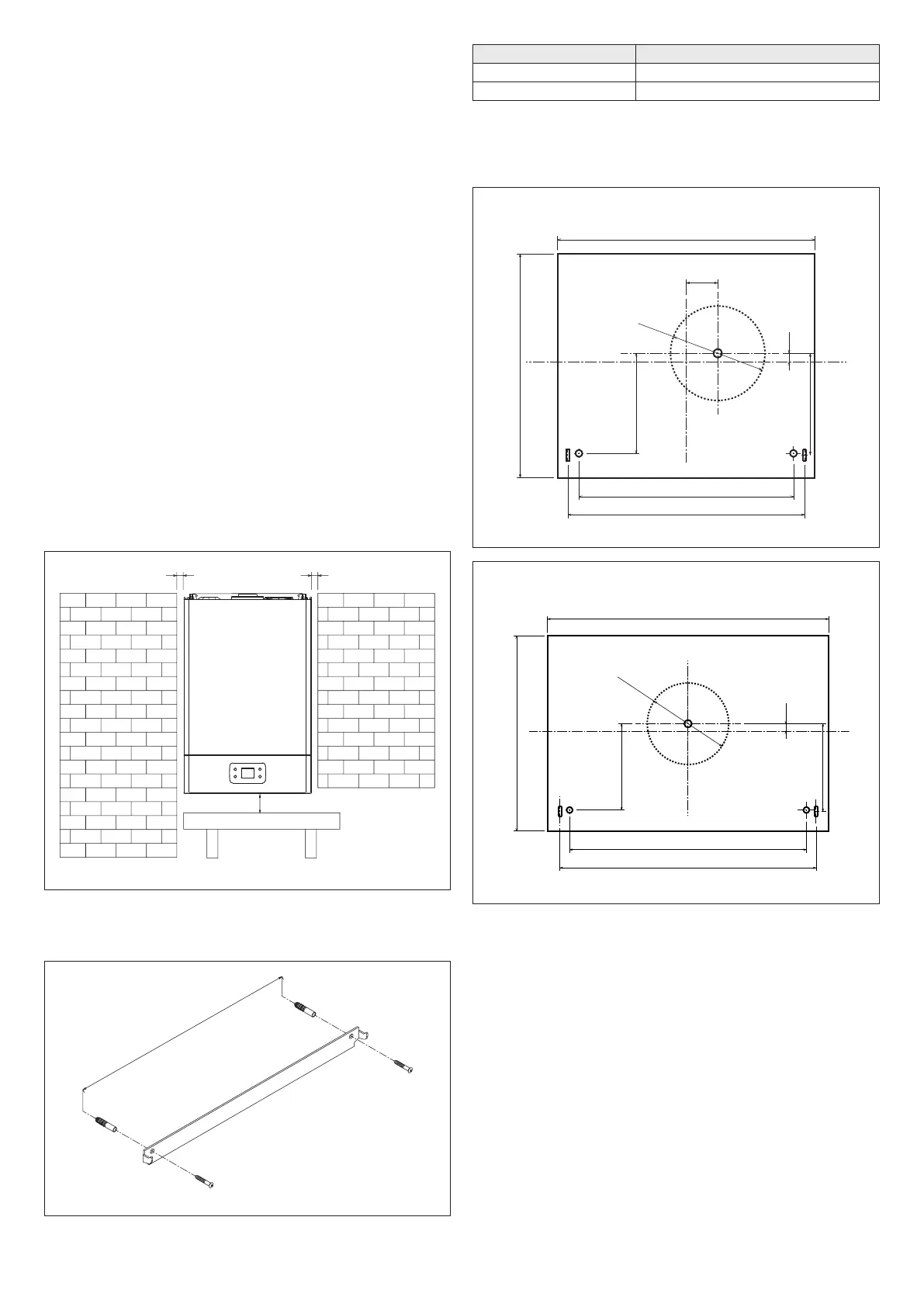
3.3 Wall mounting
3.3.1 Models for indoor installation
The appliance must be installed on a suitable wall:
- the appliance should never be closed in a unit or niche; there should be
a gap of at least 20 mm between the side walls and the appliance, so
maintenance work can be carried out;
200
Fig. 5
- once the position of the appliance has been established, position the
template supplied and mark the position of the holes, then remove it
and drill 2 Ø 8 holes
L
Fig. 6
L
Models 11-13 250 cm
Models 17 320 cm
- repositionthetemplateandxitwiththeplugssupplied
- the most common type of rear and horizontal outlet is described below;
Guidethewalltemplatensintotheslotsonthepapertemplate
- mark the centre of the pipe hole;
- drill a hole Ø 110 mm as indicated on the paper template
Models 11-13
36.7
250
276
116.6
116.6
10
ø110
Fig. 7
Models 17
116.6
118.6
10
320
346
ø110
Fig. 8
- cut the pipes to the correct length according to the thickness of the wall.
Ifdonecorrectly,the60mmØuepipeshouldprotrudeby7.5mmwith
respect to the 100 mm Ø air duct
- insertthespecicpipemadeupoftwoconcentricpipesintheholein
the wall
 Loading...