7 Main Menu Device Setup LB 470 Level
56925BA2 Rev. 03, 11/2017
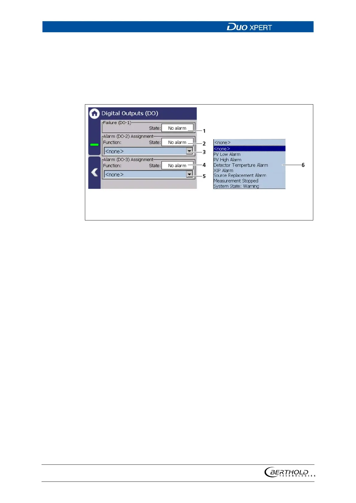
Digital Outputs (DO)
Device settings | Setup | Output | Digital Outputs (DO)
The signals of the digital outputs are switched via potential-free relay contacts. The
contacts are controlled "fail safe", ie, in the event of an alarm, the current at the
relay coil drops and the NO contact (normally open) is opened. The wiring diagrams
in chapter 5 show the relay contacts in the de-energized state.
State DO-1 (ACTIVE / PASSIVE)
State DO-2 (ACTIVE / PASSIVE)
Selection arrow Function DO-2
State DO-3 (ACTIVE / PASSIVE)
Selection arrow Function DO-3
Function selection
124 Digital Outputs
The alarm relays 1 and 2 can be assigned to the following functions in the event of
an alarm:
The relay switches when the value at Device
Setup | Setup | Alarms | PV alarm settings is
underrun.
The relay switches if the value under Device
Setup | Setup | Alarms | PV Alarm Settings is
exceeded.
Detector temperature Alarm
The relay switches when values set at Device
Setup | Setup | Alarms | Det.-
function are exceeded or underrun.
The relay switches when detection is acti-
vated at
Device settings | Setup | Signal
processing | XIP and interference was de-
tected.
The relay switches when notification at De-
vice settings | Setup | Signal processing |
Source replacement is activated and interfer-
ence is detected.
The relay switches on during tests or other
states where the m
For example, Simulation, plate space meas-
urement, and detector update.
The relay switches when the event message
″Warning″ is displayed.